Figure 16
System Control Switch
(SC Model Only)
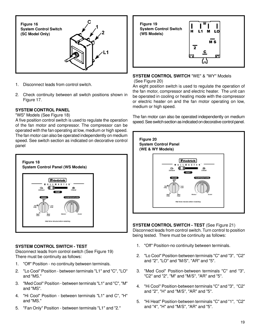
Figure 19
System Control Switch
(WS Models)
1.Disconnect leads from control switch.
2.Check continuity between all switch positions shown in Figure 17.
SYSTEM CONTROL PANEL
"WS" Models (See Figure 18)
A five position control switch is used to regulate the operation of the fan motor and compressor. The compressor can be operated with the fan operating at low, medium or high speed. The fan motor can also be operated independently on medium speed. See switch section as indicated on decorative control panel
Figure 18
System Control Panel (WS Models)
SYSTEM CONTROL SWITCH "WE" & "WY" Models (See Figure 20)
An eight position switch is used to regulate the operation of the fan motor, compressor and electric heater. The unit can be operated in cooling or heating mode with the compressor or electric heater on and the fan motor operating on low, medium or high speed.
The fan motor can also be operated independently on medium speed. See switch section as indicated on decorative control panel.
Figure 20
System Control Panel
(WE & WY Models)
SYSTEM CONTROL SWITCH - TEST (See Figure 21) Disconnect leads from control switch. Turn control to position being tested. There must be continuity as follows:
SYSTEM CONTROL SWITCH - TEST
Disconnect leads from control switch (See Figure 19) There must be continuity as follows:
1."Off" Position - no continuity between terminals.
2."Lo Cool" Position - between terminals "L1" and "C", "LO" and "MS."
3."Med Cool" Position - between terminals "L1" and "C", "M" and "MS".
4."Hi Cool" Position - between terminals "L1" and C", "H" and "MS."
5."Fan Only" Position - between terminals "L1" and "2."
1."Off"
2."Lo Cool"
3."Med Cool"
4."Hi Cool"
5."Hi Heat"
19