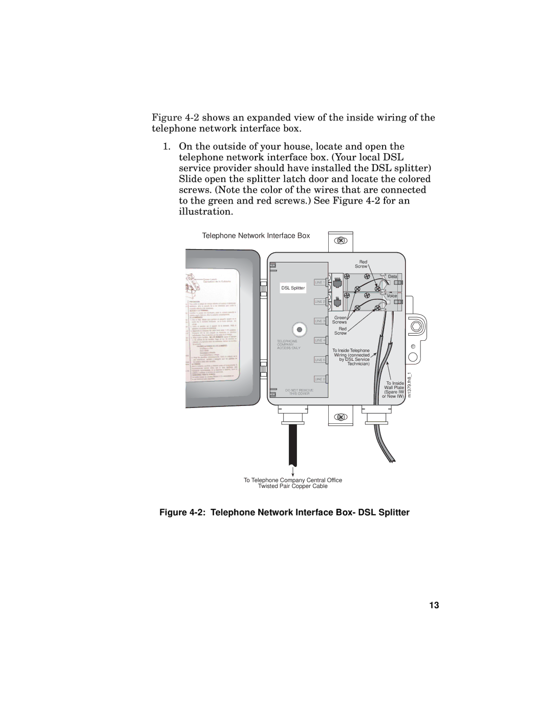
Figure 4-2 shows an expanded view of the inside wiring of the telephone network interface box.
1.On the outside of your house, locate and open the telephone network interface box. (Your local DSL service provider should have installed the DSL splitter) Slide open the splitter latch door and locate the colored screws. (Note the color of the wires that are connected to the green and red screws.) See Figure 4-2 for an illustration.
Telephone Network Interface Box
DSL Splitter
TELEPHONE
COMPANY
ACCESS ONLY
DO NOT REMOVE
THIS COVER
LINE 1
LINE 2
LINE 3
LINE 4
LINE 5
LINE 6
Red
Screw
Green |
Screws |
Red |
Screw |
To Inside Telephone
Wiring (connected ![]()
by DSL Service
Technician)
Data
Voice
To Inside Wall Plate (Spare IW or New IW)
m1379.fh8_1
To Telephone Company Central Office
Twisted Pair Copper Cable
Figure 4-2: Telephone Network Interface Box- DSL Splitter
13