MAP3735FC, MAP3147FC specifications
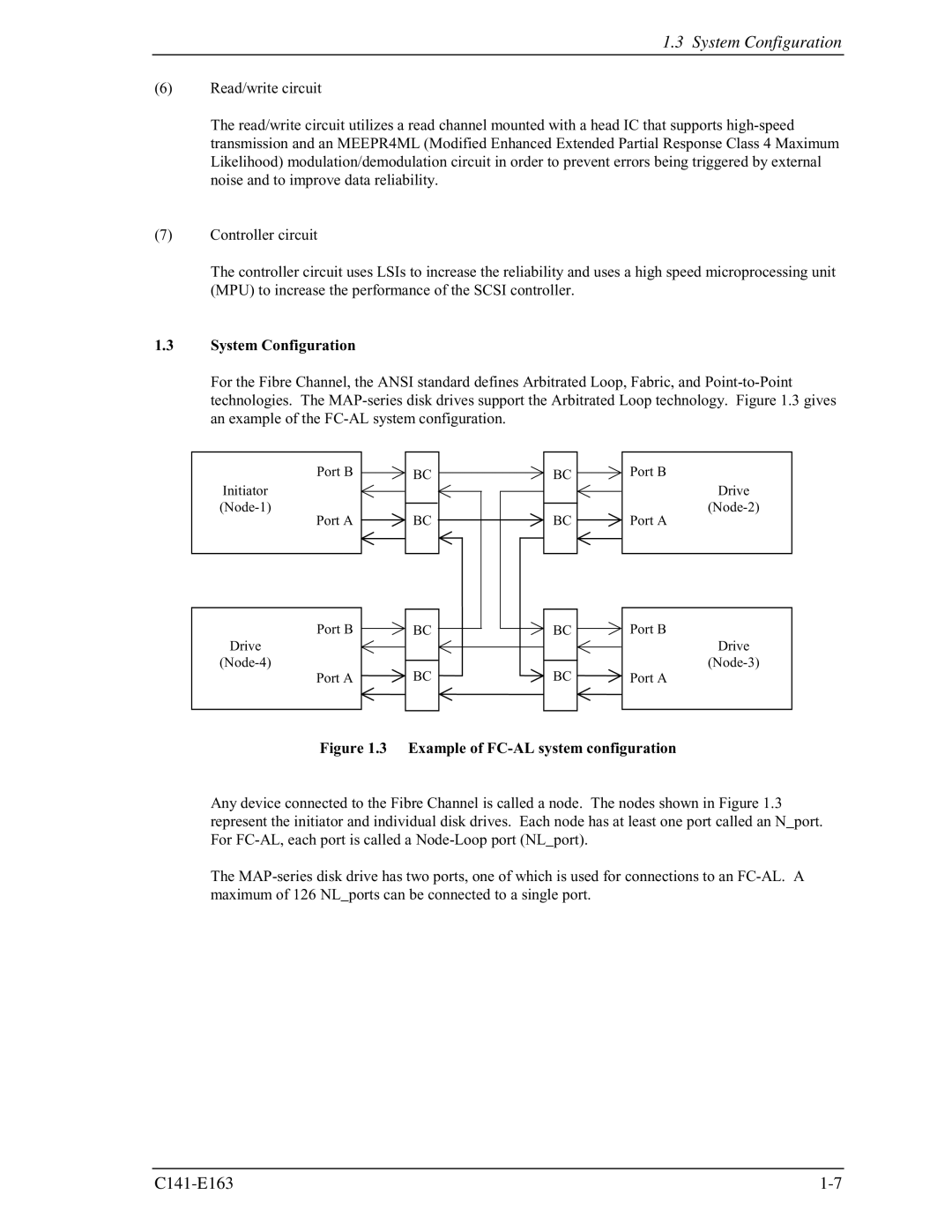
Fujitsu has been a prominent player in the hard disk drive market, with its MAP3147FC and MAP3735FC models standing out in terms of performance and reliability. These drives are engineered to meet the growing demands of enterprise applications, providing robust solutions for data storage in critical environments.The Fujitsu MAP3147FC, with a capacity of 147 GB, is optimized for high-speed data access and storage efficiency. This 3.5-inch SCSI drive operates at a rotational speed of 15,000 RPM, ensuring rapid data retrieval and minimized latency, making it ideal for applications requiring quick transaction processing. It features a 4 Gbps Fibre Channel interface, which enhances connectivity and system integration, promoting seamless communication between devices in storage area networks.
On the other hand, the MAP3735FC model offers a higher capacity of 300 GB. It shares similar specifications with its counterpart, including the 15,000 RPM speed, which guarantees top-notch performance for mission-critical applications. The MAP3735FC, like the MAP3147FC, incorporates advanced technologies such as Command Queuing, which optimizes the execution of multiple read and write commands in a queue. This feature is particularly beneficial in environments with high I/O demands, improving overall system throughput and efficiency.
Both drives utilize sophisticated error correction techniques, ensuring data integrity and reliability. They are equipped with features like S.M.A.R.T. (Self-Monitoring, Analysis, and Reporting Technology), which continuously monitors the health of the drives and helps predict potential failures, allowing for proactive maintenance and data protection.
In terms of physical characteristics, both models are designed to withstand the rigors of continuous operation. They are built with a rugged casing to protect against vibration and shock, making them suitable for use in enterprise-level servers and storage systems. Their design also allows for efficient heat dissipation, which is critical for maintaining optimal performance during extended use.
In summary, Fujitsu's MAP3147FC and MAP3735FC hard drives embody a combination of high speed, reliability, and advanced features tailored for enterprise environments. Their robust performance, large storage capacities, and reliable error correction technologies make them an excellent choice for businesses looking to optimize their data storage solutions and ensure seamless operation in demanding applications. With Fujitsu's commitment to quality and innovation, these models continue to meet the evolving needs of the data storage industry.

