03$+ 3528&70$18$
59,6,215&25
7KLVSDJHLVLQWHQWLRQDOO\OHIWEODQN
$18$/25*$1,=$7,21 03$+
7KLVPDQXDO
7KLVSDJHLVLQWHQWLRQDOO\OHIWEODQN
35$
QWKLVPDQXDOGLVNGULYHVPD\EHUHIHUUHGWRDVGULYHVRUGHYLFHV
Dpsoh
RQYHQWLRQVIRU$OHUW0HVVDJHV
7KHIROORZLQJDUHWKHDOHUWVLJQDOVDQGWKHLUPHDQLQJV
03257$17
$%,/,7&37,21
7KLVSDJHLVLQWHQWLRQDOO\OHIWEODQN
217176
+$375 7+2529,&235$7,21
+$375 ,175$
+$375 235$7,216 HYLFH5HVSRQVHWRWKH5HVHW
Sdjh
DEOHW\SHGHWHFWLRQXVLQJ&%/,VLJQDO
Dwdexiihufrqiljxudwlrq
$%/6
7KLVSDJHLVLQWHQWLRQDOO\OHIWEODQN
DUJHFDSDFLW\
UURU5DWH
Hdwxuhv Xqfwlrqvdqgshuirupdqfh Rpsdfw
+LJKVSHHG7UDQVIHUUDWH
Lghwhpshudwxuhudqjh
$YHUDJHSRVLWLRQLQJWLPH
$GDSWDELOLW\ 3RZHUVDYHPRGH
Rzqrlvhdqgyleudwlrq
UURUFRUUHFWLRQDQGUHWU\E\
Ulwhfdfkh
6SHFLILFDWLRQV
Hljkw DSDFLW\XQGHUWKH/%$PRGH
5LSSOH
0RXQWLQJ 2UGHU1R 5HPDUNV
3RZHU5HTXLUHPHQWV QSXW9ROWDJH
0DLPXP
Xuuhqwdqgsrzhuglvvlsdwlrq
Page
+XPLGLW\ ‡2SHUDWLQJ
‡1RQRSHUDWLQJ
‡7KHUPDO*UDGLHQW
$FRXVWLF1RLVH 7DEOHOLVWVWKHDFRXVWLFQRLVHVSHFLILFDWLRQ
‡PVGXUDWLRQ \SLFDOQRGDPDJH
Zlwkrxwqrquhfryhuhghuuruv
‡PVGXUDWLRQ
5HOLDELOLW\ 0HDQWLPHEHWZHHQIDLOXUHV07%
8QUHFRYHUDEOHUHDGHUURU
6HUYLFHOLIH
Vxuidfhwhpshudwxuh Dwddvvxudqfhlqwkhhyhqwrisrzhuidloxuh
3RVLWLRQLQJHUURU
Device Configuration System Configuration
Disk drive outerview
Page
System Configuration ATA interface
2 1 drive connection
03257$17
Installation Conditions
Dimensions
8VHWKHULVWVWUDS6KRFNDEVRUELQJPDW
+DQGOLQJ&DXWLRQV
Hqhudoqrwhv
Ljxuh +DQGOLQJFDXWLRQV Qvwdoodwlrq
Direction
Limitation of side-mounting
PCA
Page
Service area
0RGH 6HWWLQJ 3LQV
DEOH&RQQHFWLRQV Hylfhfrqqhfwru
3RZHUVXSSO\FRQQHFWRU&1 $7$LQWHUIDFHFRQQHFWRU&1
$7$
Rqwdfw
Deohfrqqhfwruvshflilfdwlrqv
Xmlwvx
Hylfhfrqqhfwlrq
Power supply connector CN1
+12V Return +5V Return
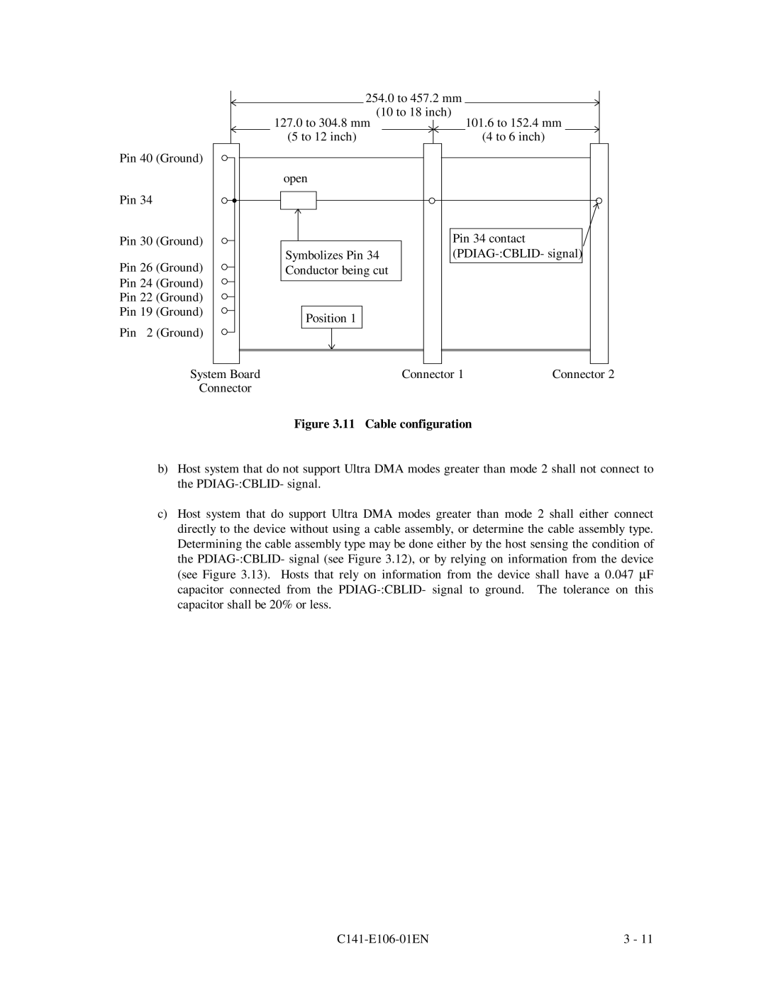
Cable configuration
Host detected CBLID- above VIH
XPSHU6HWWLQJV Rfdwlrqrivhwwlqjmxpshuv
3RZHU&RQQHFWRU
Ljxuh -XPSHUORFDWLRQ
Factory default setting
15 Factory default setting Jumper configuration
17 Jumper setting of Cable Select
18 Example 1 of Cable Select
MPF3102AH
MPF3153AH
MPF3204AH
Outline
Disk
Ljxuh +HDGVWUXFWXUH
+HDG
03$70RGHO
6SLQGOH
Air filter
6HUYRFLUFXLW
6SLQGOHPRWRUGULYHUFLUFXLW
Rqwuroohuflufxlw 0DMRUIXQFWLRQVDUHOLVWHGEHORZ
630
Qwhuidfh
+DUG LVN Rqwuroohu
Ljxuh 03$+%ORFNGLDJUDP
Power-on Sequence
Power-on operation sequence
Self-calibration contents
Self-calibration execution timechart
Command processing during self-calibration
Ulwhflufxlw
5HDGZULWH&LUFXLW
5HDGZULWHSUHDPSOLILHU3UH$03
Ulwhsuhfrpshqvdwlrq
$GDSWLYHHTXDOLHUFLUFXLW
5HDGFLUFXLW
3URJUDPPDEOHILOWHU
9LWHUELGHWHFWLRQFLUFXLW
\QWKHVLHUFLUFXLW
=RQH \OLQGHU
6HUYR&RQWURO
Servo control circuit
Physical sector servo configuration on disk surface
Page
Data-surface servo format
Servo frame format
6HUYR Udph Ljxuh Vhuyriudphvlqhdfkwudfn ULWHUHDGUHFRYHU\
326 $60
55HFRYHU\LHOG 6HUYR Udph
6HUYRPDUN$60660
Actuator motor control
Spindle motor control
Page
+$375 ,175$
Physical Interface Interface signals
Reset
Signal assignment on the connector
Signal assignment on the interface connector
DA1 PDIAG-, C Blid DA0 DA2
Hstrobe
Dior
Hdmardy
Pidag
Iordy
Ddmardy
Dstrobe
Logical Interface
1 I/O registers
I/O registers
DA2 DA1 DA0
Command block registers
Icrc UNC Idnf Abrt TK0NF Amnf
Page
DEV HS3 HS2 HS1 HS0
BSY Drdy DSC DRQ ERR
Page
Host Commands
Control block registers
Srst
Command code and parameters
Command code and parameters 1
Command code and parameters 2
Command descriptions
LBA
LBA LSB
1F2 HSC Transfer sector count 1F1 HFR = 0 or C141-E106-01EN
Read Multiple XC4
Execution example of Read Multiple command
BSY Drdy Intrq DRQ
1F3 HSN Start sector No
1F4 HCL End cylinder No. LSB
LBA
Write Multiple XC5
LBA
Write Verify X3C
LBA
1F2 HSC 1F1 HER Error information C141-E106-01EN
Initialize Device Parameters
Identify Device XEC
7DEOH ,QIRUPDWLRQWREHUHDGE\,17,9,&FRPPDQGRI
7DEOH ,QIRUPDWLRQWREHUHDGE\,17,9,&FRPPDQGRI
0DQXIDFWXUHUVUHFRPPHQGHG0$WUDQVIHUF\FOHWLPHQV@
LW5HVHUYHG
LW5HOHDVH,QWHUUXSWVXSSRUWHG
LW 8QGHILQHG
SET Features XEF
Identify Device DMA XEE
1RRSHUDWLRQ
Ulyhrshudwlrqprgh
Qdeohvwkhzulwhfdfkhixqfwlrq
Qdeohwkhdgydqfhgsrzhupdqdjhphqwixqfwlrq
Page
SET Multiple Mode XC6
Execute Device Diagnostic
Diagnostic code
LBA LSB
LBA LSB
Write Buffer XE8
Page
Page
Page
Page
XFF
Page
Dwwulexwhydoxhlqirupdwlrqwrwkhkrvw
Xqfwlrq
60$575HDG$WWULEXWH9DOXHV
60$575HDG$WWULEXWH7KUHVKROGV
Page
Format of device attribute value data
1FE 1FF
10 Format of insurance failure threshold value data
Page
Page
$WFRPPDQGLVVXDQFH,2UHJLVWHUVVHWWLQJFRQWHQWV
86+&$&+¨
1277KLVFRPPDQGPD\WDNHORQJHUWKDQVWRFRPSOHWH
+&0
11 Contents of security password
Page
Page
85,75=/2&.K
VVXLQJWKLVFRPPDQGGXULQJ/2&.02UHWXUQVWKH$ERUWHG&RPPDQGHUURU
85,7673$6625K
7KLVFRPPDQGHQDEOHVDXVHUSDVVZRUGRUPDVWHUSDVVZRUGWREHVHW
12 Contents of Security SET Password data
Page
SET MAX Address F9
Read Native MAX Address F8
Page
Error posting
14 Command code and parameters
Command Protocol
∙ Execute Device Diagnostic ∙ Initialize Device Parameters
Data transferring commands from device to host
IOR
BSY Drdy DRQ Intrq
DRQ Intrq
IOCS16
BSY Drdy DRQ Intrq
7KHGHYLFHUHVHWV,1754WKHLQWHUUXSWVLJQDO
‡‡‡‡
‡‡‡ ‡‡‡‡ Ljxuh 5,76&7256FRPPDQGSURWRFRO
Commands without data transfer
∙ SET MAX Address ∙ Read Native MAX Address
BSY Drdy Intrq
∙ Read Multiple ∙ Sleep ∙ Write Multiple
Other commands
DMA data transfer commands
∙ Read DMA ∙ Write DMA
DRQ Dmarq Dmack
IOW
Ultra DMA feature set Overview
Phases of operation
Pausing an Ultra DMA data in burst
Data in transfer
Terminating an Ultra DMA data in burst
Page
Page
Pausing an Ultra DMA data out burst
Data out transfer
Terminating an Ultra DMA data out burst
Page
Ultra DMA CRC rules
6HULHVWHUPLQDWLRQUHTXLUHGIRU8OWUD0$
7DEOH 5HFRPPHQGHGVHULHVWHUPLQDWLRQIRU8OWUD0$ 6LJQDO
9FF
Timing PIO data transfer
DIOR-/DIOW
Multiword data transfer
Dmarq Dmack DIOR-/DIOW
Ghylfh
8OWUD0$GDWDWUDQVIHU
QLWLDWLQJDQ8OWUD0$GDWDLQEXUVW
Krvw
Name Mode Comment MIN MAX
When sender terminates a burst
16 Ultra DMA data burst timing requirements 2
Dwkrvw
6XVWDLQHG8OWUD0$GDWDLQEXUVW
Dwghylfh
Ljxuh 6XVWDLQHG8OWUD0$GDWDLQEXUVW
+RVWSDXVLQJDQ8OWUD0$GDWDLQEXUVW
Ghylfh 1RWHV
Ljxuh +RVWSDXVLQJDQ8OWUD0$GDWDLQEXUVW
HYLFHWHUPLQDWLQJDQ8OWUD0$GDWDLQEXUVW
+0$5
Ljxuh HYLFHWHUPLQDWLQJDQ8OWUD0$GDWDLQEXUVW
+RVWWHUPLQDWLQJDQ8OWUD0$GDWDLQEXUVW
Ljxuh +RVWWHUPLQDWLQJDQ8OWUD0$GDWDLQEXUVW
+6752% Krvw
QLWLDWLQJDQ8OWUD0$GDWDRXWEXUVW
GHYLFHW8
Ljxuh ,QLWLDWLQJDQ8OWUD0$GDWDRXWEXUVW
Dwghylfh 1RWH
6XVWDLQHG8OWUD0$GDWDRXWEXUVW
+6752%
Ljxuh 6XVWDLQHG8OWUD0$GDWDRXWEXUVW
HYLFHSDXVLQJDQ8OWUD0$GDWDRXWEXUVW
$5 Ghylfh +6752% Krvw
Ljxuh HYLFHSDXVLQJDQ8OWUD0$GDWDRXWEXUVW
+RVWWHUPLQDWLQJDQ8OWUD0$GDWDRXWEXUVW
Ljxuh +RVWWHUPLQDWLQJDQ8OWUD0$GDWDRXWEXUVW
Ljxuh HYLFHWHUPLQDWLQJDQ8OWUD0$GDWDRXWEXUVW
Power-on and reset
BSY Dasp
Pdiag Dasp
This page is intentionally left blank
Chapter Operations
Response to power-on
Pdiag
Response to hardware reset
Response to software reset
Response to diagnostic command
Default parameters
MPF3102AH MPF3153AH MPF3204AH
Ljxuhvkrzvdqhdpsohdvvxplqjwkhuhlvqrwudfnvnhz
Rjlfdodgguhvv
+6PRGH
Ljxuh $GGUHVVWUDQVODWLRQHDPSOHLQ&+6PRGH
Ljxuh $GGUHVVWUDQVODWLRQHDPSOHLQ/%$PRGH
$PRGH
Ljxuhvkrzvdqhdpsohridvvxplqjwkhuhlvqrwudfnvnhz
3RZHU6DYH
Gohprgh
$FWLYHPRGH
$GHYLFHHQWHUVWKHDFWLYHPRGHXQGHUWKHIROORZLQJFRQGLWLRQV
5HVHWKDUGZDUHRUVRIWZDUH
Power commands
QGH
6SDUHDUHD
6SDUHF\OLQGHUIRUDOWHUQDWLYHDVVLJQPHQW
Ljxuh 6HFWRUVOLSSURFHVVLQJ
$OWHUQDWHF\OLQGHUDVVLJQPHQW
$OWHUQDWH \OLQGHU$OUHDG\
Khqdzulwhhuururffxuvdqgwkhhuurugrhvqrwuhfryhuhg
5HDG$KHDG&DFKH
Dwdexiihufrqiljxudwlrq
Ljxuh Dwdexiihufrqiljxudwlrq
Caching operation
∙ Read Sector S ∙ Read Multiple ∙ Read DMA
∙ Write Sectors ∙ Write DMA ∙ Write Multiple
Usage of read segment
HAP
DAP
Mis-hit data Empty data
Read-ahead data New read-ahead data Hit data
HAP set to hit position for data transfer
Partially hit data Lack data
Write Cache
∙ Write Sectors ∙ Write Multiple ∙ Write DMA
XVLQHVV3ODQQLQJ