2. WIRING
2.1 Connections
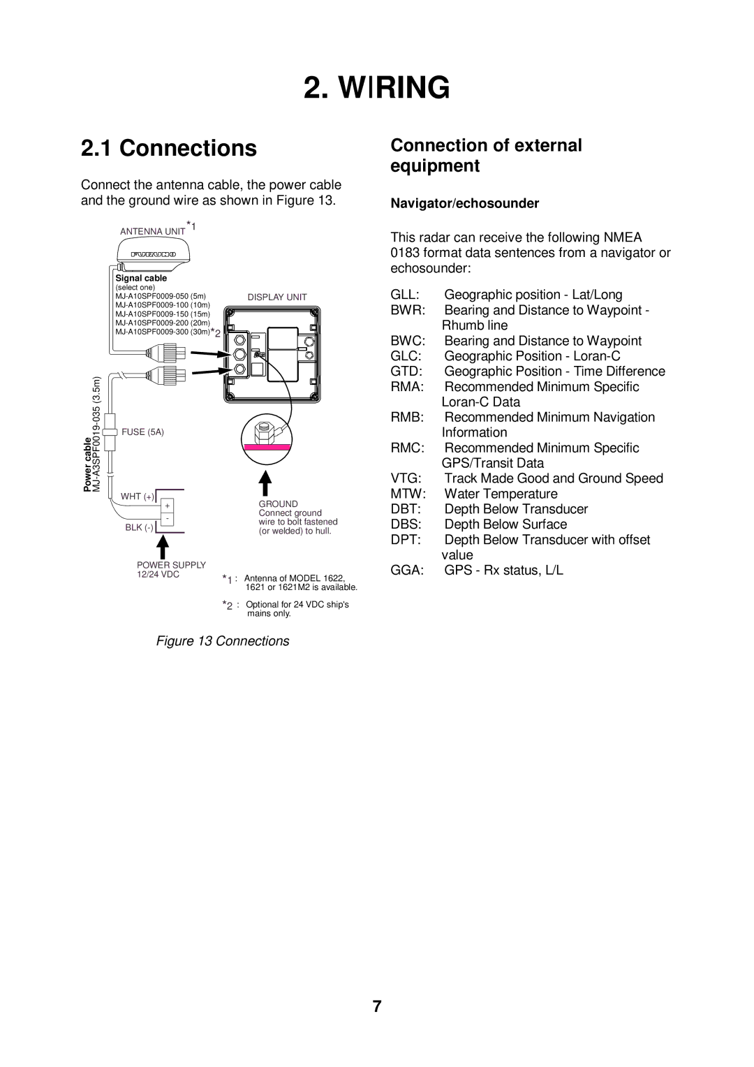
Connect the antenna cable, the power cable and the ground wire as shown in Figure 13.
ANTENNA UNIT*1
Signal cable (select one)
DISPLAY UNIT | ||
(10m) |
| |
(15m) |
| |
(20m) |
| |
(30m)*2 |
| |
Connection of external equipment
Navigator/echosounder
This radar can receive the following NMEA 0183 format data sentences from a navigator or echosounder:
GLL: | Geographic position - Lat/Long |
BWR: | Bearing and Distance to Waypoint - |
| Rhumb line |
BWC: | Bearing and Distance to Waypoint |
GLC: | Geographic Position - |
GTD: | Geographic Position - Time Difference |
Power cable
![]() FUSE (5A)
FUSE (5A)
WHT (+)
+
-
BLK
GROUND Connect ground wire to bolt fastened (or welded) to hull.
RMA: | Recommended Minimum Specific |
| |
RMB: | Recommended Minimum Navigation |
| Information |
RMC: | Recommended Minimum Specific |
| GPS/Transit Data |
VTG: | Track Made Good and Ground Speed |
MTW: | Water Temperature |
DBT: | Depth Below Transducer |
DBS: | Depth Below Surface |
DPT: | Depth Below Transducer with offset |
| value |
POWER SUPPLY |
|
|
12/24 VDC | *1 | : Antenna of MODEL 1622, |
|
1621 or 1621M2 is available.
*2 : Optional for 24 VDC ship's mains only.
Figure 13 Connections
GGA: GPS - Rx status, L/L |
7