3.4Adjustments for Technicians
1) Magnetron heater voltage
Magnetron heater voltage is formed at the MD Board of the antenna unit and preadjusted at the factory for use with any length of signal cable. Therefore no adjustment is required. However, verify heater voltage as follows:
![]() CAUTION
CAUTION
Lift the radome cover slowly.
The antenna radiator may be caught by the screw holes in the radome cover.
If you feel the radiator is caught by the screw holes, lower the cover, turn it a few degree and then lift it again.
![]() Screw holes
Screw holes ![]()
![]() (4 places)
(4 places)
Note: Turn the power on when measuring magnetron heater voltage.
1.Dismount the shield plate.
MD board under the shield plate
Figure 27 MD board
2.Turn on the power. Do not transmit the radar.
3.Connect a multimeter, set to 10 V DC range, between #6(+) and
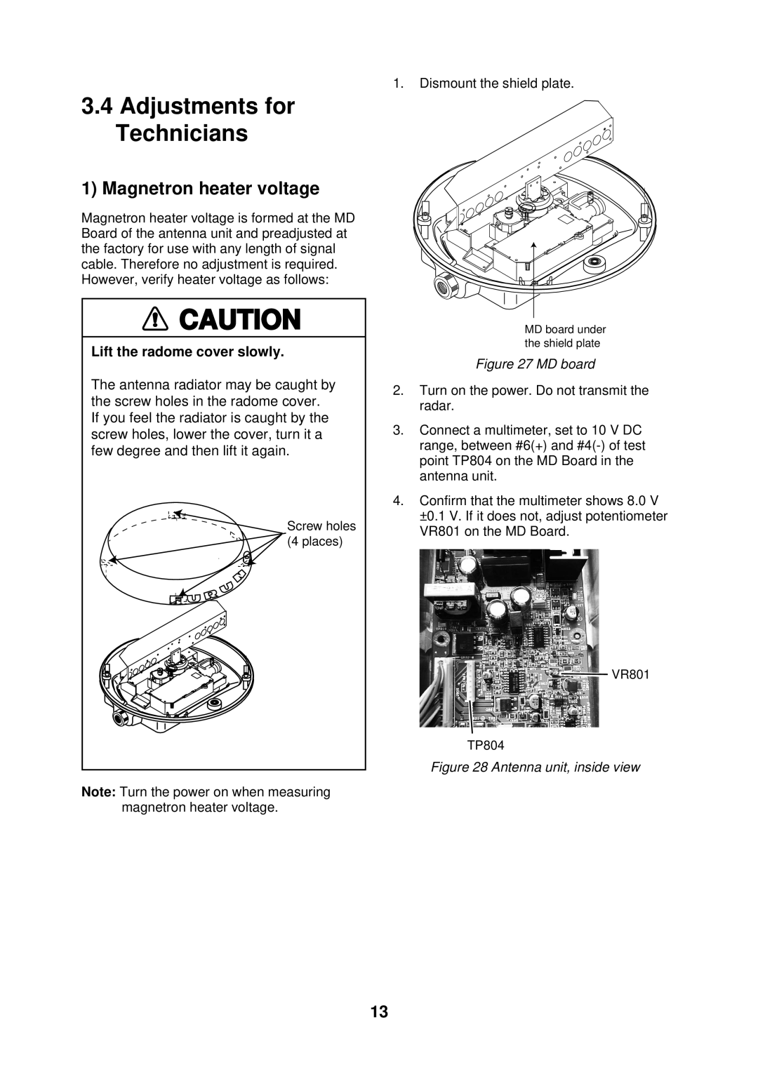
4.Confirm that the multimeter shows 8.0 V ±0.1 V. If it does not, adjust potentiometer VR801 on the MD Board.
VR851
![]() VR801
VR801
TP804
Figure 28 Antenna unit, inside view
13