| Direct | Heading |
|
| path | line |
|
| Target |
|
|
| Indirect |
|
|
| path |
|
|
| Obstruction |
|
|
| Antenna (mast, funnel. |
|
|
| etc.) |
| True |
Indirect | Target |
| |
| Indirect | echo | |
path | Direct | echo |
|
| path |
|
|
| Own | Heading |
|
| line |
| |
| ship |
| |
|
|
|
True ![]() echo
echo
Bridge
![]() Indirect
Indirect
Indirectecho echo
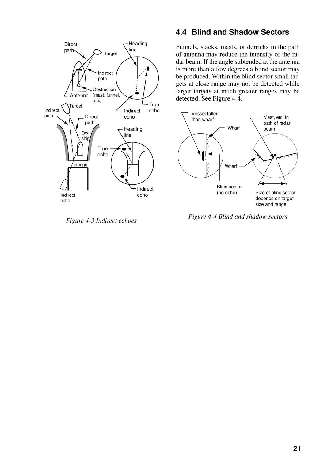
Figure 4-3 Indirect echoes
4.4 Blind and Shadow Sectors
Funnels, stacks, masts, or derricks in the path of antenna may reduce the intensity of the ra- dar beam. If the angle subtended at the antenna is more than a few degrees a blind sector may be produced. Within the blind sector small tar- gets at close range may not be detected while larger targets at much greater ranges may be detected. See Figure
Vessel taller
than wharf |
| Mast, etc. in | ||
| ||||
| path of radar | |||
|
| Wharf |
| |
|
|
| beam | |
|
|
| ||
|
|
|
| Wharf |
|
|
|
|
|
|
|
|
|
|
|
|
|
|
|
|
|
|
|
|
|
| |
|
|
|
|
|
|
|
|
|
|
|
|
| |
|
|
|
|
|
|
|
|
|
|
|
|
| |
|
|
|
|
|
|
|
|
|
|
|
|
| |
|
|
|
|
|
|
|
|
|
|
|
| ||
|
|
|
|
|
|
|
|
|
|
|
|
|
|
|
|
|
|
|
|
|
|
|
|
|
|
| |
|
|
|
|
|
|
|
|
|
|
|
|
| |
|
| Blind sector |
|
|
|
|
|
|
|
| |||
|
|
|
|
|
|
|
|
|
| ||||
|
|
|
|
|
|
|
|
|
| ||||
|
| (no echo) |
|
|
|
|
|
| |||||
|
|
| Size of blind | sector | |||||||||
|
|
|
|
|
|
|
| depends on target | |||||
|
|
|
|
|
|
|
| size and range. | |||||
Figure 4-4 Blind and shadow sectors
21