External E/S interface installation kit
Part | Type, Q'ty | Code No. | Q'ty |
|
|
|
|
External E/S Interface Assy. | - | - | 1 |
|
|
|
|
XH Connector Assy. | 1 | ||
|
|
|
|
Screw | M3x6 | 4 | |
|
|
|
|
Screw | M3x8 | 1 | |
|
|
|
|
Cable Ties | No.249 | 1 | |
|
|
|
|
1.Remove the display unit cover.
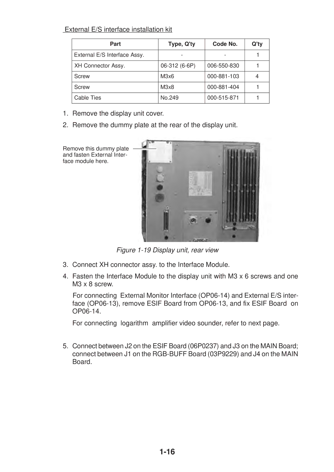
2.Remove the dummy plate at the rear of the display unit.
Remove this dummy plate and fasten External Inter- face module here.
Figure 1-19 Display unit, rear view
3.Connect XH connector assy. to the Interface Module.
4.Fasten the Interface Module to the display unit with M3 x 6 screws and one M3 x 8 screw.
For connecting External Monitor Interface
For connecting logarithm amplifier video sounder, refer to next page.
5.Connect between J2 on the ESIF Board (06P0237) and J3 on the MAIN Board; connect between J1 on the