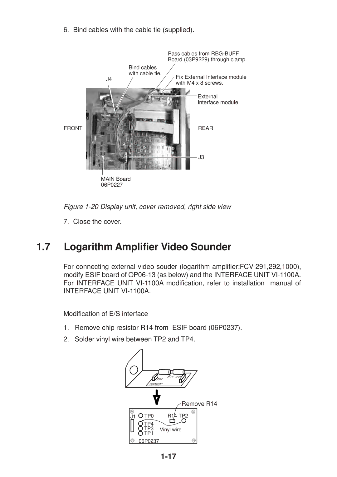
6. Bind cables with the cable tie (supplied).
|
| Pass cables from |
|
| Board (03P9229) through clamp. |
|
| Bind cables |
|
| with cable tie. |
| J4 | Fix External Interface module |
| with M4 x 8 screws. | |
|
| |
|
| External |
|
| Interface module |
FRONT |
| REAR |
J3
MAIN Board 06P0227
Figure 1-20 Display unit, cover removed, right side view
7.Close the cover.
1.7Logarithm Amplifier Video Sounder
For connecting external video souder (logarithm
Modification of E/S interface
1.Remove chip resistor R14 from ESIF board (06P0237).
2.Solder vinyl wire between TP2 and TP4.
R14 TP2
TP4
06P0237
Remove R14
J1 TP0 | R14 TP2 |
TP4 |
|
TP3 | Vinyl wire |
TP1 |
|
06P0237 |
|