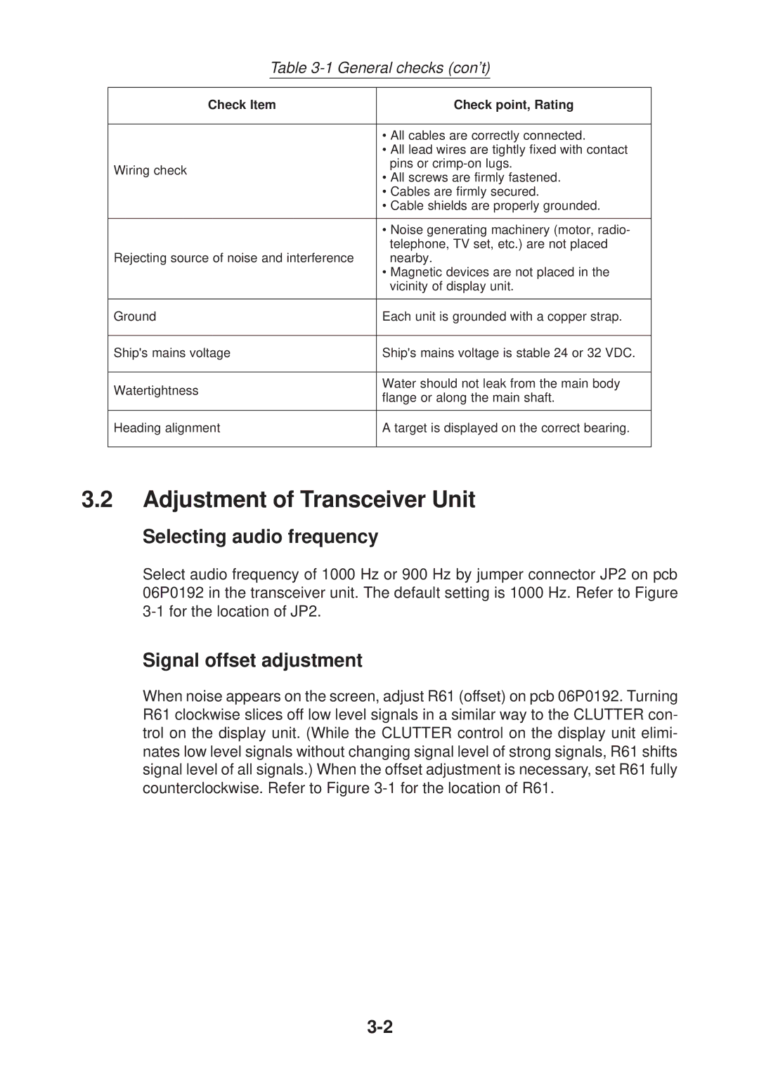
Table 3-1 General checks (con’t)
Check Item | Check point, Rating | |
|
| |
| • All cables are correctly connected. | |
| • All lead wires are tightly fixed with contact | |
Wiring check | pins or | |
• All screws are firmly fastened. | ||
| ||
| • Cables are firmly secured. | |
| • Cable shields are properly grounded. | |
|
| |
| • Noise generating machinery (motor, radio- | |
| telephone, TV set, etc.) are not placed | |
Rejecting source of noise and interference | nearby. | |
| • Magnetic devices are not placed in the | |
| vicinity of display unit. | |
|
| |
Ground | Each unit is grounded with a copper strap. | |
|
| |
Ship's mains voltage | Ship's mains voltage is stable 24 or 32 VDC. | |
|
| |
Watertightness | Water should not leak from the main body | |
flange or along the main shaft. | ||
| ||
|
| |
Heading alignment | A target is displayed on the correct bearing. | |
|
|
3.2Adjustment of Transceiver Unit
Selecting audio frequency
Select audio frequency of 1000 Hz or 900 Hz by jumper connector JP2 on pcb 06P0192 in the transceiver unit. The default setting is 1000 Hz. Refer to Figure
Signal offset adjustment
When noise appears on the screen, adjust R61 (offset) on pcb 06P0192. Turning R61 clockwise slices off low level signals in a similar way to the CLUTTER con- trol on the display unit. (While the CLUTTER control on the display unit elimi- nates low level signals without changing signal level of strong signals, R61 shifts signal level of all signals.) When the offset adjustment is necessary, set R61 fully counterclockwise. Refer to Figure