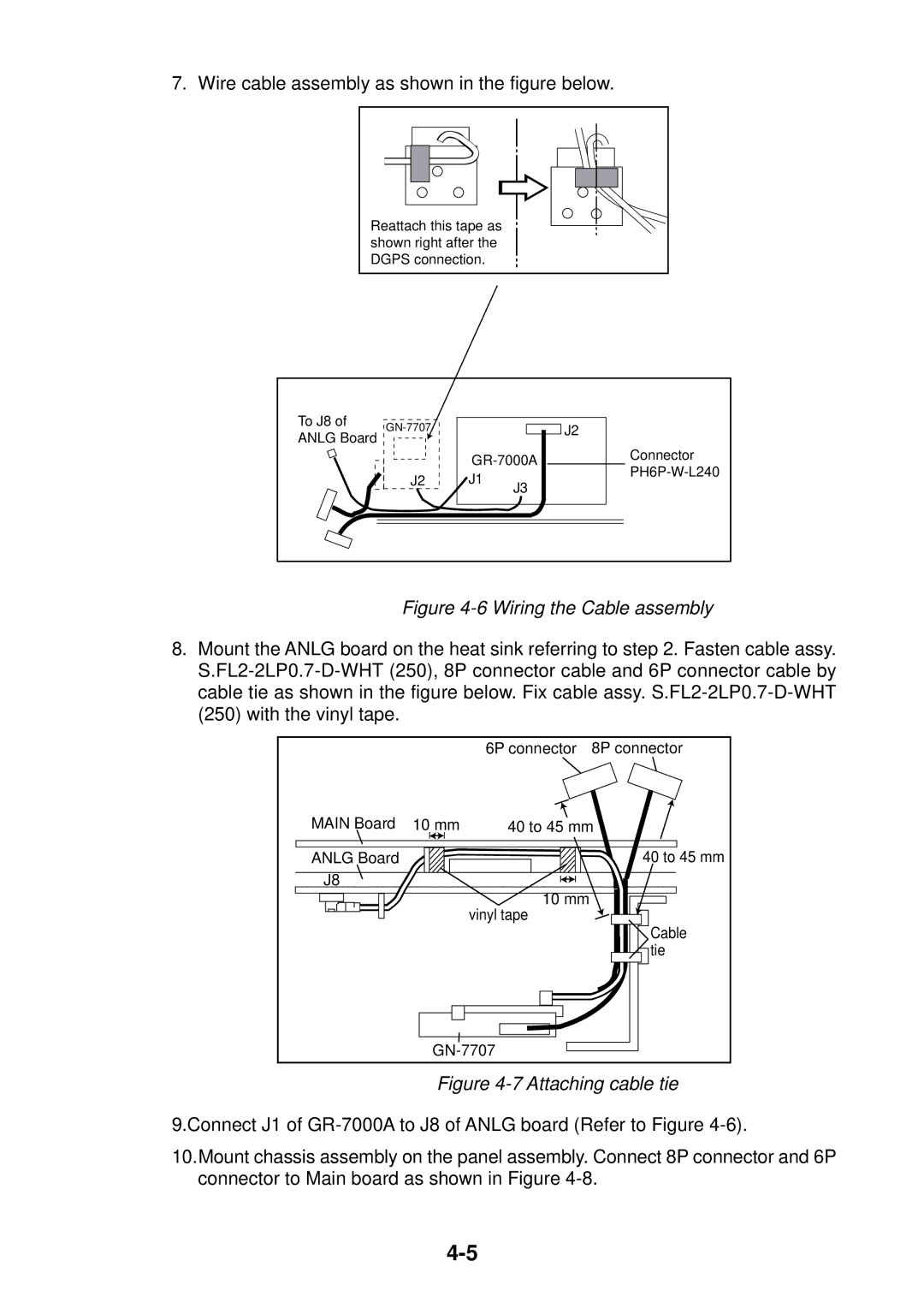
7. Wire cable assembly as shown in the figure below.
Reattach this tape as shown right after the DGPS connection.
To J8 of ANLG Board
J2
J2
J1
J3
Connector
Figure 4-6 Wiring the Cable assembly
8.Mount the ANLG board on the heat sink referring to step 2. Fasten cable assy.
|
| 6P connector | 8P connector |
MAIN Board | 10 mm | 40 to 45 mm | |
ANLG Board |
|
| 40 to 45 mm |
J8 |
|
|
|
|
| 10 mm |
|
|
| vinyl tape |
|
|
|
| Cable |
|
|
| tie |
|
| ||
Figure 4-7 Attaching cable tie
9.Connect J1 of
10.Mount chassis assembly on the panel assembly. Connect 8P connector and 6P connector to Main board as shown in Figure