5.2 Wiring
5.2.1 Wiring between HSD modem and router
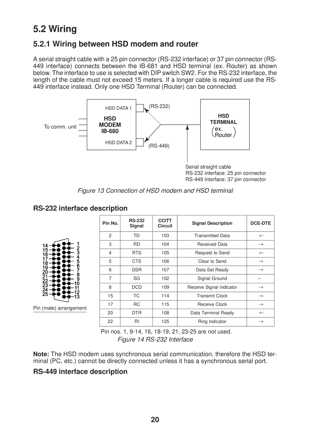
A serial straight cable with a 25 pin connector
To comm. unit
HSD DATA 1
HSD
MODEM
IB-680
HSD DATA 2
HSD
TERMINAL
ex. Router
Serial straight cable
Figure 13 Connection of HSD modem and HSD terminal
RS-232 interface description
|
|
| Pin No. | CCITT | Signal Description |
| ||
|
|
| Signal | Circuit | ||||
|
|
|
|
|
| |||
|
|
|
|
|
| |||
| 2 | TD | 103 | Transmitted Data | ← | |||
|
|
|
|
|
| |||
| 3 | RD | 104 | Received Data | → | |||
|
|
|
|
|
| |||
| 4 | RTS | 105 | Request to Send | ← | |||
|
|
|
|
|
| |||
| 5 | CTS | 106 | Clear to Send | → | |||
|
|
|
|
|
| |||
| 6 | DSR | 107 | Data Set Ready | → | |||
|
|
|
|
|
| |||
| 7 | SG | 102 | Signal Ground | – | |||
|
|
|
|
|
| |||
| 8 | DCD | 109 | Receive Signal Indicator | → | |||
|
|
|
|
|
| |||
| 15 | TC | 114 | Transmit Clock | → | |||
|
|
|
|
|
| |||
Pin (male) arrangement | 17 | RC | 115 | Receive Clock | → | |||
|
|
|
|
| ||||
20 | DTR | 108 | Data Terminal Ready | ← | ||||
|
|
| ||||||
| ||||||||
|
|
|
|
|
| |||
| 22 | RI | 125 | Ring Indicator | → | |||
|
|
|
|
|
|
|
| |
Pin nos. 1,
Figure 14 RS-232 Interface
Note: The HSD modem uses synchronous serial communication, therefore the HSD ter- minal (PC, etc.) cannot be directly connected unless it has a synchronous serial port.
RS-449 interface description
20
