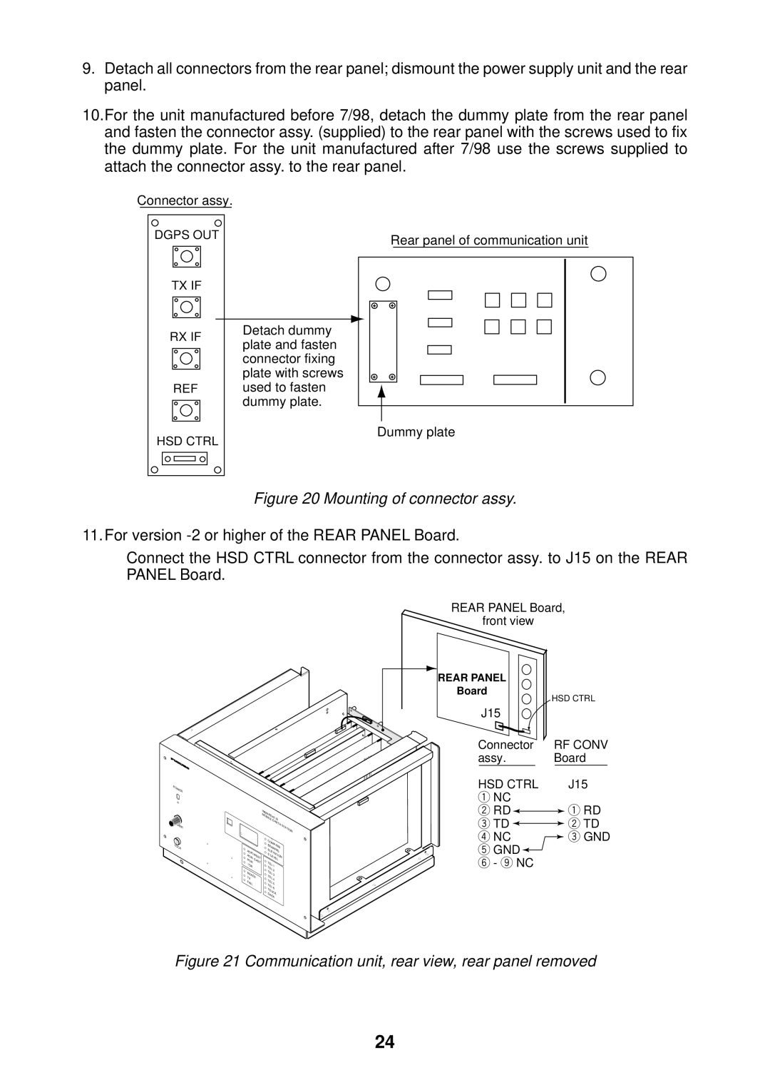
9.Detach all connectors from the rear panel; dismount the power supply unit and the rear panel.
10.For the unit manufactured before 7/98, detach the dummy plate from the rear panel and fasten the connector assy. (supplied) to the rear panel with the screws used to fix the dummy plate. For the unit manufactured after 7/98 use the screws supplied to attach the connector assy. to the rear panel.
Connector assy.
DGPS OUT | Rear panel of communication unit |
|
TX IF
RX IF | Detach dummy | |
plate and fasten | ||
| ||
| connector fixing | |
| plate with screws | |
REF | used to fasten | |
| dummy plate. | |
HSD CTRL | Dummy plate | |
|
Figure 20 Mounting of connector assy.
11.For version
Connect the HSD CTRL connector from the connector assy. to J15 on the REAR PANEL Board.
POWER |
DIMMER |
LOCK |
| |
EARTH | STATION |
|
|
| COMPASS | ||
|
| BEARING | ||
AOR- |
| ELEVATION | ||
| S | LEVEL | ||
| ||||
POR | EAST | TEL |
| |
I |
| 1 | ||
OR |
| TEL | ||
|
| 2 | ||
READY | TEL | 3 | ||
TX |
| TEL | 4 | |
FAIL |
| TEL | 5 | |
| TEL | |||
|
| 6 | ||
|
| TELEX | ||
|
| DATA | ||
REAR PANEL Board,
front view
REAR PANEL
Board
|
|
|
| HSD CTRL | |||
J15 |
|
|
|
| |||
Connector | RF CONV | ||||||
assy. |
| Board | |||||
|
|
|
|
|
| ||
HSD CTRL |
|
| J15 | ||||
1 NC |
|
|
|
| |||
2 RD |
|
|
|
| 1 RD | ||
|
|
|
| ||||
3 TD |
|
|
|
| 2 TD | ||
|
|
|
| ||||
4 NC |
|
| 3 GND | ||||
5 GND |
|
|
|
| |||
6 - 9 NC |
|
|
|
| |||
Figure 21 Communication unit, rear view, rear panel removed
24
