Antenna cable | Position of R135 | |
length | ||
| ||
|
| |
10 to 40 m | Marked position (default position) | |
|
| |
More than 40 m | Fully clockwise (max. output power) | |
|
|
4.Remove the CPU2 Board from the communication unit. See Figure 19 for location.
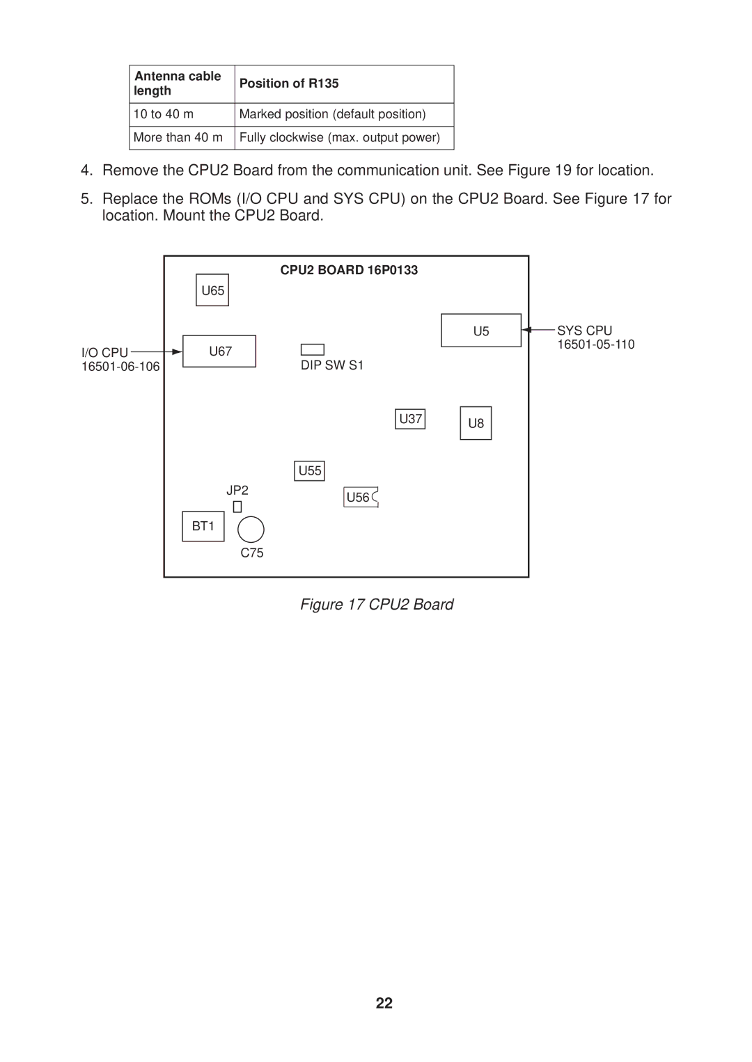
5.Replace the ROMs (I/O CPU and SYS CPU) on the CPU2 Board. See Figure 17 for location. Mount the CPU2 Board.
|
|
|
| CPU2 BOARD 16P0133 |
|
|
|
|
| U65 |
|
| |
|
|
|
| U5 |
| SYS CPU |
|
|
|
|
| ||
I/O CPU |
|
| U67 |
| ||
|
| DIP SW S1 |
|
| ||
|
|
|
| |||
|
|
| ||||
U37 U8
U55
JP2
BT1
U56
C75
Figure 17 CPU2 Board
22
