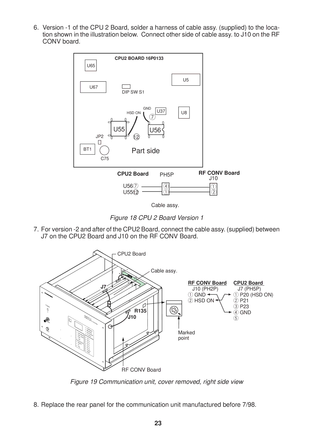
6.Version
U65
U67
JP2
BT1
CPU2 BOARD 16P0133
U5
DIP SW S1
| GND |
|
HSD ON | U37 | U8 |
7 | ||
U55 | U56 |
|
12
Part side
C75
CPU2 Board PH5P | RF CONV Board |
| J10 |
U567
U5512
4
1
1
2
Cable assy.
Figure 18 CPU 2 Board Version 1
7.For version
POWER |
DIMMER |
LOCK |
J7
|
| INMARSAT- |
| ||
|
| MOBILE | B |
| |
|
|
|
| EARTH | STATION |
|
|
|
|
| |
|
| COMPASS |
| ||
|
| BEARING |
| ||
AOR- |
| ELEVATION | |||
| S | LEVEL |
| ||
|
| ||||
POR | EAST | TEL |
|
| |
I |
| 1 |
| ||
OR |
| TEL |
| ||
|
| 2 |
| ||
READY | TEL | 3 |
| ||
TX |
| TEL | 4 |
| |
FAIL |
| TEL | 5 |
| |
| TEL |
| |||
|
| 6 |
| ||
|
| TELEX |
| ||
|
| DATA |
| ||
CPU2 Board |
| |
Cable assy. |
| |
RF CONV Board | CPU2 Board | |
J10 (PH2P) | J7 (PH5P) | |
1 GND | 1 P20 (HSD ON) | |
2 HSD ON | 2 P21 | |
R135 | 3 P23 | |
4 GND | ||
J10 | ||
5 | ||
Marked |
| |
point |
|
RF CONV Board
Figure 19 Communication unit, cover removed, right side view
8. Replace the rear panel for the communication unit manufactured before 7/98.
23