12. Attach the rear panel and mount the power supply unit.
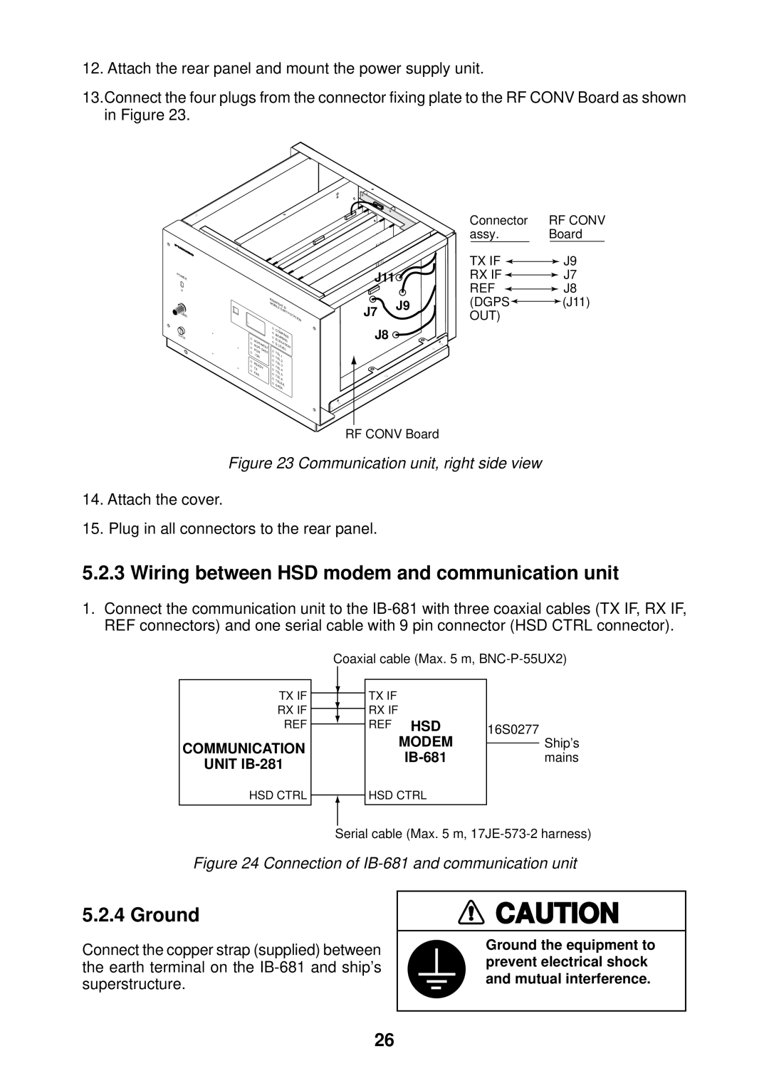
13.Connect the four plugs from the connector fixing plate to the RF CONV Board as shown in Figure 23.
POWER |
DIMMER |
LOCK |
|
|
| |||
|
|
|
| EARTH | STATION |
|
|
|
|
| |
|
| COMPASS |
| ||
|
| BEARING |
| ||
AOR- |
| ELEVATION | |||
| S | LEVEL |
| ||
|
| ||||
POR | EAST | TEL |
|
| |
I |
| 1 |
| ||
OR |
| TEL |
| ||
|
| 2 |
| ||
READY | TEL | 3 |
| ||
TX |
| TEL | 4 |
| |
FAIL |
| TEL | 5 |
| |
| TEL |
| |||
|
| 6 |
| ||
|
| TELEX |
| ||
|
| DATA |
| ||
J11 |
J7 | J9 |
| |
J8 |
|
Connector | RF CONV | ||||||
assy. | Board | ||||||
TX IF |
|
|
|
|
| J9 | |
|
|
|
| ||||
RX IF |
|
|
|
|
| J7 | |
|
|
|
| ||||
REF |
|
|
|
|
| J8 | |
|
|
|
| ||||
(DGPS |
|
|
|
| (J11) | ||
|
|
|
| ||||
OUT) |
|
|
|
| |||
RF CONV Board
Figure 23 Communication unit, right side view
14.Attach the cover.
15.Plug in all connectors to the rear panel.
5.2.3 Wiring between HSD modem and communication unit
1.Connect the communication unit to the
TX IF
RX IF
REF
COMMUNICATION
UNIT IB-281
Coaxial cable (Max. 5 m,
TX IF |
|
|
RX IF |
|
|
REF HSD | 16S0277 | |
MODEM |
| Ship’s |
| ||
| mains | |
HSD CTRL
HSD CTRL
Serial cable (Max. 5 m,
Figure 24 Connection of IB-681 and communication unit
5.2.4 Ground
Connect the copper strap (supplied) between the earth terminal on the
![]() CAUTION
CAUTION
Ground the equipment to prevent electrical shock and mutual interference.
26