GarrettCom 500-Series manual B4.0 Installation, B5.0 Operation, B6.0 Troubleshooting

Models: 500-Series

1 34
Download 34 pages 1.63 Kb
Page 34
Image 34

Magnum 500-Series Switching Hubs

Installation and User Guide (08/98)


B4.0 INSTALLATION

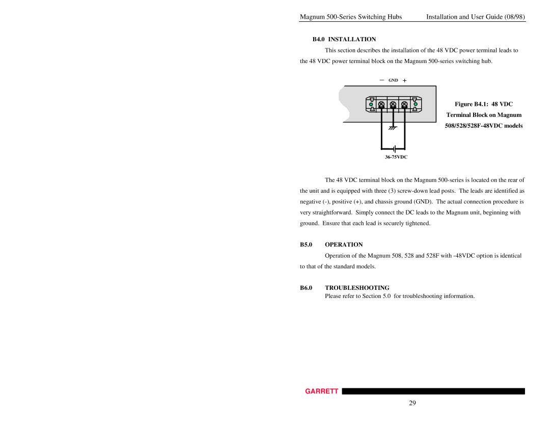
This section describes the installation of the 48 VDC power terminal leads to the 48 VDC power terminal block on the Magnum 500-series switching hub.

_ GND +

Figure B4.1: 48 VDC

Terminal Block on Magnum 508/528/528F-48VDC models

36-75VDC

The 48 VDC terminal block on the Magnum 500-series is located on the rear of the unit and is equipped with three (3) screw-down lead posts. The leads are identified as negative (-), positive (+), and chassis ground (GND). The actual connection procedure is very straightforward. Simply connect the DC leads to the Magnum unit, beginning with ground. Ensure that each lead is securely tightened.

B5.0 OPERATION

Operation of the Magnum 508, 528 and 528F with -48VDC option is identical to that of the standard models.

B6.0 TROUBLESHOOTING

Please refer to Section 5.0 for troubleshooting information.

GARRETT

29

Page 34
Image 34
GarrettCom 500-Series manual B4.0 Installation, B5.0 Operation, B6.0 Troubleshooting