Magnum | Installation and User Guide (08/98) |
|
|
Designed for use in departments with multiple workgroups, in remote offices and in network traffic centers, the Magnum
2.2.1Magnum 500-Series chassis
| Magnum |
|
| Switching Hub |
|
GARRETT |
|
|
|
|
|
PWR | 10Mb |
|
LK /RX | FDX |
|
|
|
|
|
|
| UPLINK |
1 | 2 | 3 | 4 | 5 | 6 | 7 | 8 |
|
|
| Magnum |
|
|
| Switching Hub |
| GA RRETT |
|
|
|
|
|
|
PWR |
| AUTO | 10M b |
L K RX | 100 Mb | L IN K | RX |
TX RX
100 | LK |
|
|
|
|
|
| UPL INK |
10 | RX |
|
|
|
|
|
|
|
F/H | F/H |
|
|
|
|
|
|
|
| 1 | 2 | 3 | 4 | 5 | 6 | 7 | 8 |
|
|
| Magnum |
|
|
|
| Switching Hub |
|
| GARRETT |
|
|
|
|
|
|
|
|
PWR |
| AUTO | 10Mb |
|
LK /RX | FDX | LK /RX | FDX |
| 100 |
| 100 |
|
|
|
|
|
|
| UPLINK |
| 10 |
| 10 |
|
|
|
|
|
|
|
|
F/H | 1 | 2 | F/H | 1 | 2 | 3 | 4 | 5 | 6 | 7 | 8 |
|
|
| Magnum |
|
|
| Switching Hub |
| GARRETT |
|
|
|
|
|
|
|
| AUTO | 10Mb |
L K RX | 100 Mb | LINK | RX |
TX | RX |
|
|
|
|
|
| LK |
|
|
|
|
|
| UPLINK |
F | H | F | H |
|
|
|
|
|
|
| |
|
|
|
| RX |
|
|
|
|
|
|
|
|
|
|
| F/H |
|
|
|
|
|
|
|
|
|
|
| 1 | 2 | 3 | 4 | 5 | 6 | 7 | 8 |
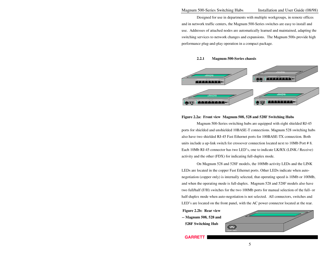
Figure 2.2a: Front view Magnum 508, 528 and 528F Switching Hubs
Magnum
On Magnum 528 and 528F models, the 100Mb activity LEDs and the LINK LEDs are located in the copper Fast Ethernet ports. Other LEDs indicate when auto- negotiation (copper only) is internally selected, that operating speed is 10Mb or 100Mb, and when the operating mode is
Figure 2.2b: Rear view
--Magnum 508, 528 and 528F Switching Hub
GARRETT
GARRETT
5
