the need for a special twisted pair
crossover cable. With the switch in
3
the UP (or LEFT) position, the RPM -
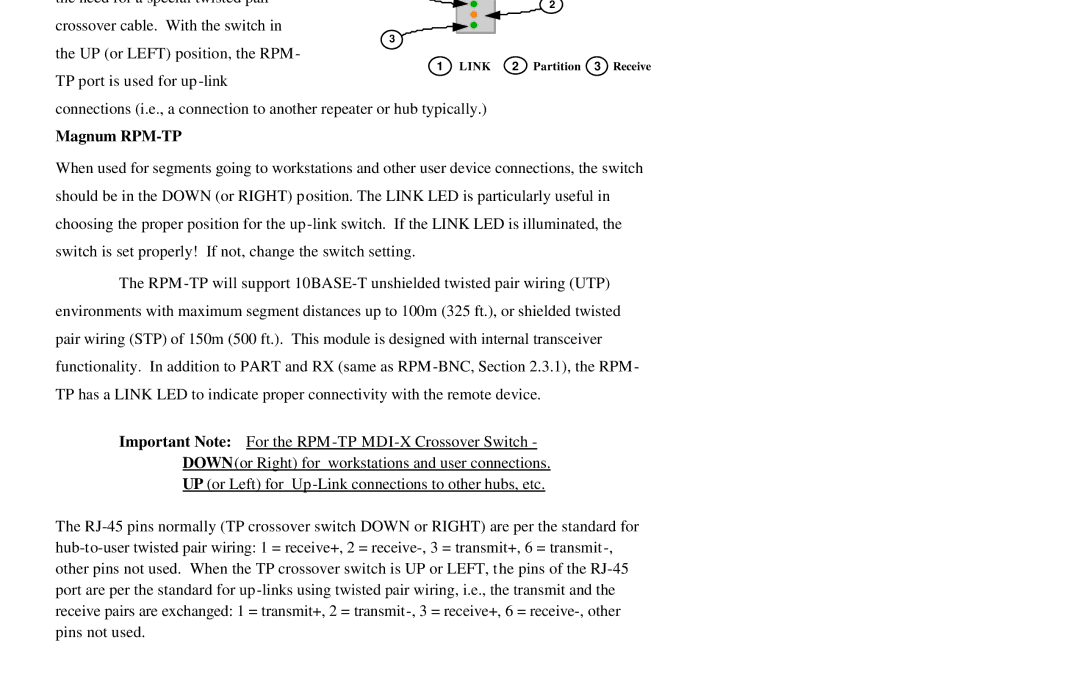
1 LINK
TP port is used for up
connections (i.e., a connection to another repeater or hub typically.)
Magnum RPM-TP
2
2 Partition 3 Receive
When used for segments going to workstations and other user device connections, the switch
should be in the DOWN (or RIGHT) position. The LINK LED is particularly useful in
choosing the proper position for the up
switch is set properly! If not, change the switch setting.
The RPM
environments with maximum segment distances up to 100m (325 ft.), or shielded twisted
pair wiring (STP) of 150m (500 ft.). This module is designed with internal transceiver
functionality. In addition to PART and RX (same as RPM
TP has a LINK LED to indicate proper connectivity with the remote device.
Important Note: For the RPM
DOWN(or Right) for workstations and user connections.
UP (or Left) for Up
The