This section describes the installation of the 48 VDC power source leads to the 48
VDC power terminal block on the Magnum 210Xs. (see figure below).
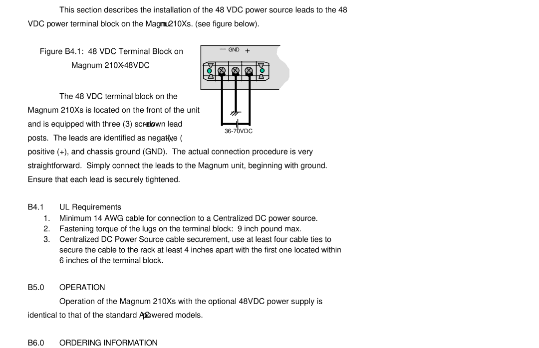
Figure B4.1: 48 VDC Terminal Block on
Magnum 210X-48VDC
The 48 VDC terminal block on the
Magnum 210Xs is located on the front of the unit
and is equipped with three (3) screw
posts. The leads are identified as negative
_ GND + |
positive (+), and chassis ground (GND). The actual connection procedure is very
straightforward. Simply connect the leads to the Magnum unit, beginning with ground.
Ensure that each lead is securely tightened.
B4.1 UL Requirements
1.Minimum 14 AWG cable for connection to a Centralized DC power source.
2.Fastening torque of the lugs on the terminal block: 9 inch pound max.
3.Centralized DC Power Source cable securement, use at least four cable ties to secure the cable to the rack at least 4 inches apart with the first one located within 6 inches of the terminal block.
B5.0 OPERATION
Operation of the Magnum 210Xs with the optional 48VDC power supply is
identical to that of the standard