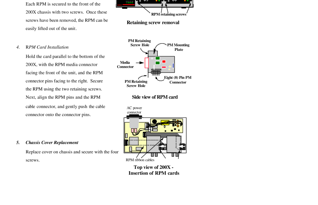
Each RPM is secured to the front of the 200X chassis with two screws. Once these screws have been removed, the RPM can be easily lifted out of the unit.
eu
PWR RX COL JAB
GARRETT
RPM retaining screws
Retaining screw removal
|
| PM Retaining |
|
4. | RPM Card Installation | Screw Hole | PM Mounting |
| Plate | ||
|
|
| |
| Hold the card parallel to the bottom of the |
|
|
| 200X, with the RPM media connector | Media |
|
| Connector |
| |
| facing the front of the unit, and the RPM |
| Eight (8) Pin PM |
| connector pins facing to the right. Secure |
| |
| PM Retaining | Connector | |
| the RPM using the two retaining screws. | Screw Hole |
|
|
|
| |
| Next, align the RPM pins and the RPM | Side view of RPM card | |
| cable connector, and gently push the cable | AC power |
|
| connector onto the connector pins. | connector |
|
|
|
| |
5. | Chassis Cover Replacement |
|
|
| Replace cover on chassis and secure with the four |
| |
| screws. | RPM ribbon cables |
|