Fiber Switches
Trademarks
GarrettCom, Inc
Contacting GarrettCom, Inc
Table of Contents
Introduction
Introduction Magnum QUAD-SERIES QPM
Personal Switches, 10/100Mb
Personal Hubs, 10Mb series
Technical Specifications
Agency Approvals
Ordering Information
Magnum Quad-Series Port Modules
Inspecting the Package and Product
Product Description Magnum Quad-Series Fiber Switches
Magnum Quad-Series chassis models
Ports Table-Top
Fiber
Quad-port modules, 100Mb fiber
Quad-port modules, 10 Mb
Quad-Port Module, RJ-45 copper
Combo 3 + 1 Quad Port Modules, 3@RJ-45 and 1@fiber
QPM-RJ45
QPRJ-MSC
Frame Buffering and Latency
Www . GarrettCom . com
Features and Benefits
„ Plug-and-Play installation for high performance switching
„ Front-mounted LEDs, world-wide AC power supply
„ 16-port, 12-port, 8-port and 4-port models
Applications
Example 1 Magnum QS580
Example 2 Magnum 8-port QS5108
Example 3 Magnum 16-port QS5116
Locating Magnum Quad-Series Switches
Location of 8-port Magnum QS580’s cooling fan exhaust
Connecting Ethernet Media
Connecting Fiber Optic ST-type, twist-lock
Ieee Standard Media Type Max. Distance Port Module Fiber
Copper
Media Ieee Standard
Connecting Fiber Optic SC-type, Snap-In
Connecting Single-Mode Fiber Optic
Rack-mounting, models QS5108 and QS5116
Table-Top or Shelf Mounting
Wall or Vertical Surface Mounting, 8-port QS580
Multiple Magnum QS5116 units rack-mounted in a 23 frame
Jumper Settings for HDX/FDX
Fiber ports, internal jumper settings
Combo ports, RJ-45 and Fiber internal jumper settings
Www . GarrettCom . com
Powering the Magnum Quad-Series Switch
10Mbps Fiber ports internal jumper settings
Quad Port Module QPM Installation
Preparation for Installing and Removing QPMs
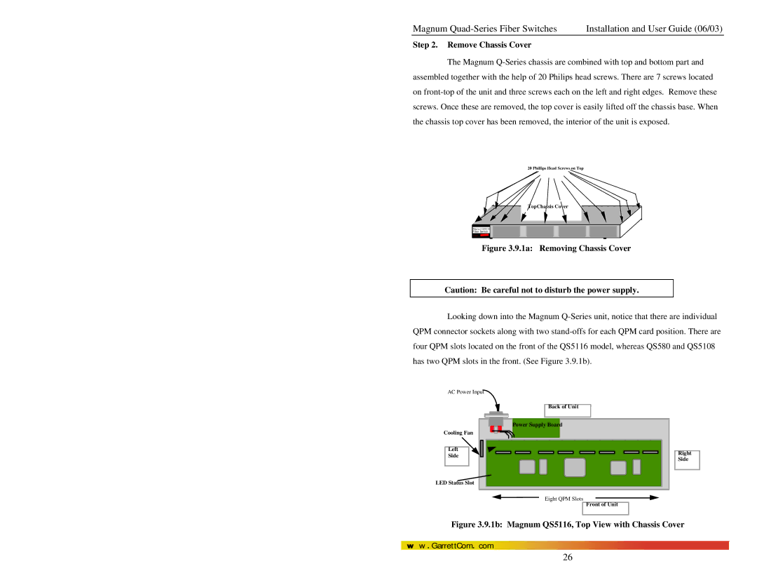
Remove Chassis Cover
1a Removing Chassis Cover
Installing QPM Cards in the Magnum Q-Series
1c Front View QPM Retaining Screws hold Face Plates
2a Inserting QPM Cards into a Magnum QS5116
Removing QPM Cards
3b Removing a QPM Card
Address Learning
Switching Functionality
Filtering and Forwarding
Status LEDs
Auto-negotiation, for Fast Ethernet copper ports
PWR
ACT
Www . GarrettCom . com
Auto-negotiation for 10 Mb ports, half- or full-duplex mode
Flow-control, Ieee 802.3x standard
Fiber Port Module
Introduction Magnum QUAD-SERIES QUAD-PORT Modules QPM
Product Description
QPM-MST, 100Mb multi-mode FX-ST Quad-port Module, twist lock
QPM-SSC 100Mbps single-mode FX-SC-type, snap-in connector
100BASE-FX Single-Mode
Small-form-factor
QPM-RJ45 Twisted Pair, 10/100Mb TP Quad-Port
10/100BASE-T and 100BASE-FX Combo Quad-Port Connectors
QPM-FP
10 Blank Face Plate
Before Calling for Assistance
No Problem Found
When Calling for Assistance
Return Material Authorization RMA Procedure
Shipping and Packaging Information
B1.0 Specifications for Magnum QUAD-SERIES Switches
Power Supply Internal -48 VDC Option
B3.0 Applications for DC Powered Ethernet Switches
Power Supply Internal 24 VDC Option
Power Supply Internal 125 or 100VDC Option
B5.0 Operation
B4.0 Installation
B4.1 UL Requirements
B6.0 Ordering Information
Magnum QS5116-125VDC
C4.0 Features and Benefits of the DUAL-SOURCE Design
C5.0 Installation
C3.0 DUAL-SOURCE OPTION, Theory of Operation
To the external Terminal Block
C5.1 UL Requirements
C6.0 Ordering Information
Example Magnum QS5116-48VDC
C7.0 Operation