GateWay Fax Systems, inc. | Model 90si Secure Fax Gateway User's Guide |
1.3Looking at your 90si
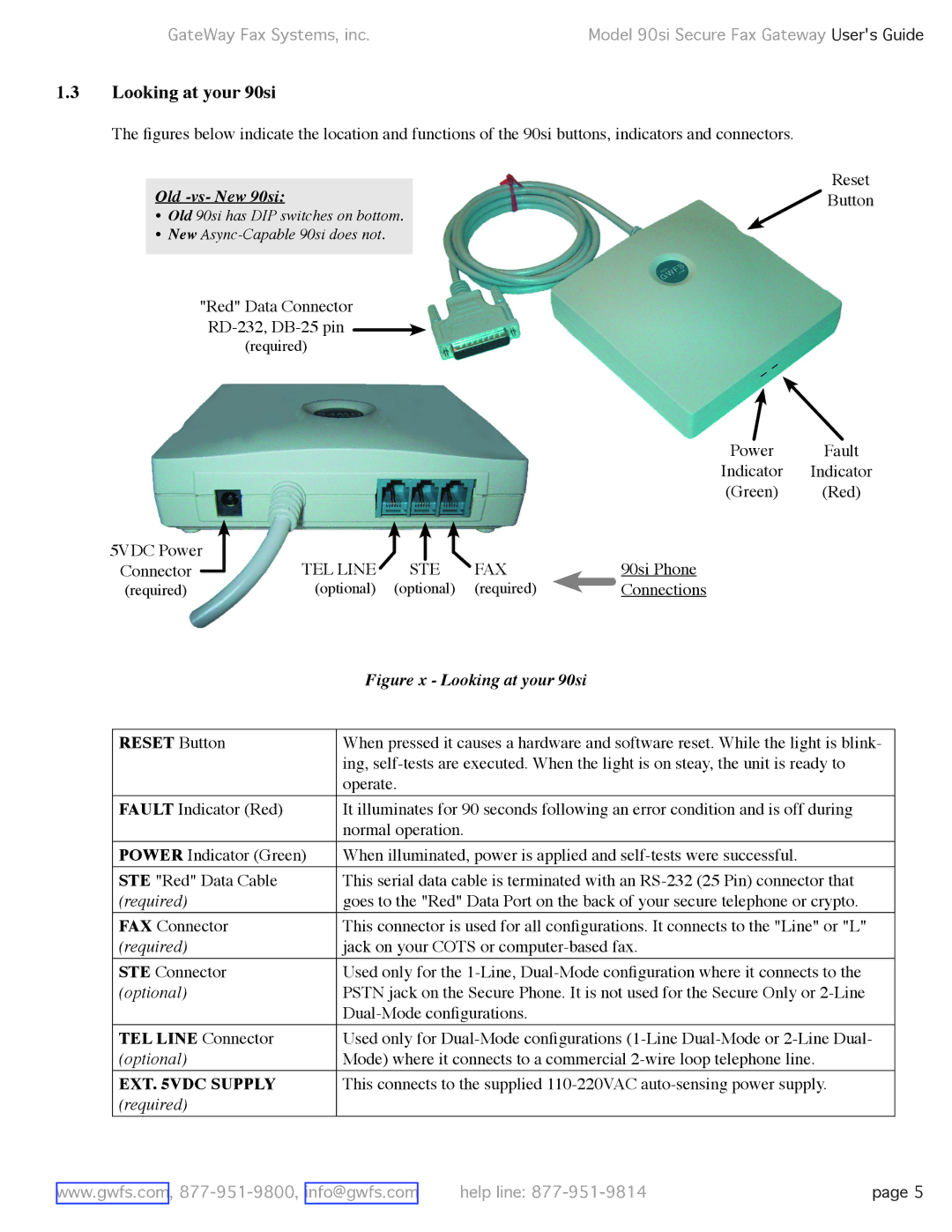
The figures below indicate the location and functions of the 90si buttons, indicators and connectors.
Reset
Old -vs- New 90si:Button
• Old 90si has DIP switches on bottom.
• New
"Red" Data Connector
(required)
Power Fault
Indicator Indicator
(Green) (Red)
5VDC Power | TEL LINE |
|
|
| FAX |
|
| |
|
|
|
|
| ||||
Connector |
| STE |
| 90si Phone | ||||
|
| |||||||
(required) | (optional) | (optional) | (required) |
| Connections | |||
| ||||||||
| Figure x - Looking at your 90si |
|
|
RESET Button | When pressed it causes a hardware and software reset. While the light is blink- |
| ing, |
| operate. |
FAULT Indicator (Red) | It illuminates for 90 seconds following an error condition and is off during |
| normal operation. |
POWER Indicator (Green) | When illuminated, power is applied and |
STE "Red" Data Cable | This serial data cable is terminated with an |
(required) | goes to the "Red" Data Port on the back of your secure telephone or crypto. |
FAX Connector | This connector is used for all configurations. It connects to the "Line" or "L" |
(required) | jack on your COTS or |
STE Connector | Used only for the |
(optional) | PSTN jack on the Secure Phone. It is not used for the Secure Only or |
| |
TEL LINE Connector | Used only for |
(optional) | Mode) where it connects to a commercial |
EXT. 5VDC SUPPLY | This connects to the supplied |
(required) |
|
www.gwfs.com, | help line: | page 5 |