REMOVE TOP CAP (on some models)

Installation Instructions

INSTALLING THE REFRIGERATOR

REFRIGERATOR LOCATION

Do not install the refrigerator where the temperature will go below 60°F(16°C) because it will not run often enoughto maintain proper temperatures.

Do not install the refrigerator where the temperature will go above 100°F(37°C) because it will not perform properly.

Install it on a floorstrong enough to supportit fully loaded.

CLEARANCES

Allow the following clearances for ease of installation, proper air circulation and plumbing and electrical connections.


Standard Depth


Models

Sides

1/8(3 mm)

Top

1(25 mm)

Back

1(25 mm)

•IMPORTANT NOTE:This refrigerator is 34-1/2deep. Doors and passagewaysleadingto the installation location must be at least36 wide in order to leave the doors and handles attached to the refrigerator

whiletransportingit into the installationlocation.

If passageways are less than 36 , the refrigerator doors and handles can easily be scratchedand damaged. The top cap and doors can be removed to allow the refrigeratorto be safely moved indoors. Start with Step A.

•If it is not necessary to remove doors, skip StepA. Leave tape and all packagingon doorsuntil the refrigeratoris in the finallocation.

•SKID REMOVAL: Tiltrefrigerator to each sideto remove skid.

•NOTE:Use a padded handtruck to movethis refrigerator.Place the refrigerator on the handtruck with a side against the truck. We stronglyrecommend that TWO PEOPLE move and complete thisinstallation.

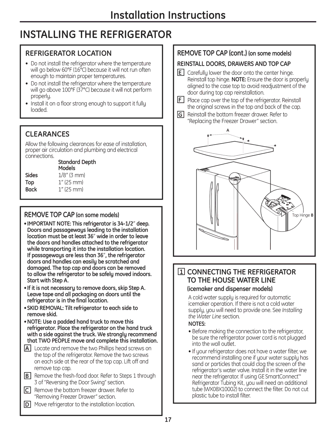
ALocate and remove the two Phillipshead screwson the top of the refrigerator.Remove the two screws on each sideat the rear of the top cap. Liftoff and remove top cap.

BRemove the fresh-food door.Refer to Steps1 through 3 of “Reversingthe Door Swing” section.

CRemove the bottom freezer drawer.Referto “RemovingFreezer Drawer” section.

DMove refrigerator to the installation location.

REMOVE TOP CAP (cont.) (on some models)

REINSTALL DOORS, DRAWERS AND TOP CAP

ECarefully lower the door onto the center hinge. Reinstall top hinge. NOTE:Ensure the door is properly aligned to the case top to avoid readjustment of the door during top cap reinstallation.

FPlace cap over the top of the refrigerator. Reinstall the original screws in the top and back of the cap.

GReinstall the bottom freezerdrawer. Refer to “Replacing the Freezer Drawer” section.

A

TopHingeB

1CONNECTING THE REFRIGERATOR

TO THE HOUSE WATER LINE

(icemaker and dispenser models)

A cold water supply is required for automatic icemaker operation. If there is not a cold water supply, you will need to provide one. See Installing the Water Line section.

NOTES:

Before making the connection to the refrigerator, be sure the refrigerator power cord is not plugged into the wall outlet.

If your refrigerator does not have a water filter,we recommend installing one if your water supply has sand or particles that could clog the screen of the refrigerator’s water valve. Install it in the water line near the refrigerator.If using GE SmartConnectRefrigerator Tubing Kit, you will need an additional tube (WX08X10002) to connect the filter.Do not cut plastic tube to install filter.

17

Page 17
Image 17
GE 200D9366P016 Refrigerator Location, Clearances, Connecting the Refrigerator To the House Water Line

200D9366P016 specifications

The GE 200D9366P016 is a notable component within General Electric's (GE) expansive portfolio, particularly recognized for its application in industrial environments requiring robust and reliable performance. This function-oriented device is often employed in various sectors, including power generation, oil and gas, and manufacturing, where operational efficiency and precision are paramount.

One of the primary features of the GE 200D9366P016 is its exceptional durability. Constructed to withstand harsh operating conditions, it is engineered with high-quality materials that resist wear and tear. This durability not only extends the lifespan of the component but also reduces maintenance needs, allowing for longer intervals between service checks, thus saving both time and money for users.

The GE 200D9366P016 incorporates advanced technologies designed to enhance efficiency. It is often embedded with smart sensing capabilities that facilitate real-time monitoring of operational parameters. This feature enables users to track performance metrics, detect potential failures before they escalate, and optimize operational workflows.

In addition to its advanced sensing technologies, the GE 200D9366P016 is designed for seamless integration with a wide range of industrial systems. This interoperability is crucial for facilities that utilize various GE products or require compatibility with third-party systems. The component's design ensures that it can be easily adapted to different configurations, thereby enabling users to customize solutions based on specific operational requirements.

The product’s user-friendly interface is another significant characteristic, allowing operators to easily interact with the device and access critical data and controls. Clear displays, coupled with intuitive controls, enable quick and efficient operation, minimizing the learning curve for new users.

Moreover, the GE 200D9366P016 is backed by extensive technical support and documentation from GE, enhancing user confidence in installation and operation. Clients benefit from a wealth of resources, including troubleshooting guides and user manuals, ensuring that they can maximize the utility of the component.

Overall, the GE 200D9366P016 stands out for its robust construction, advanced technological integration, seamless compatibility, and user-centric design, making it a preferred choice for industries that prioritize reliability and efficiency in their operations.