6
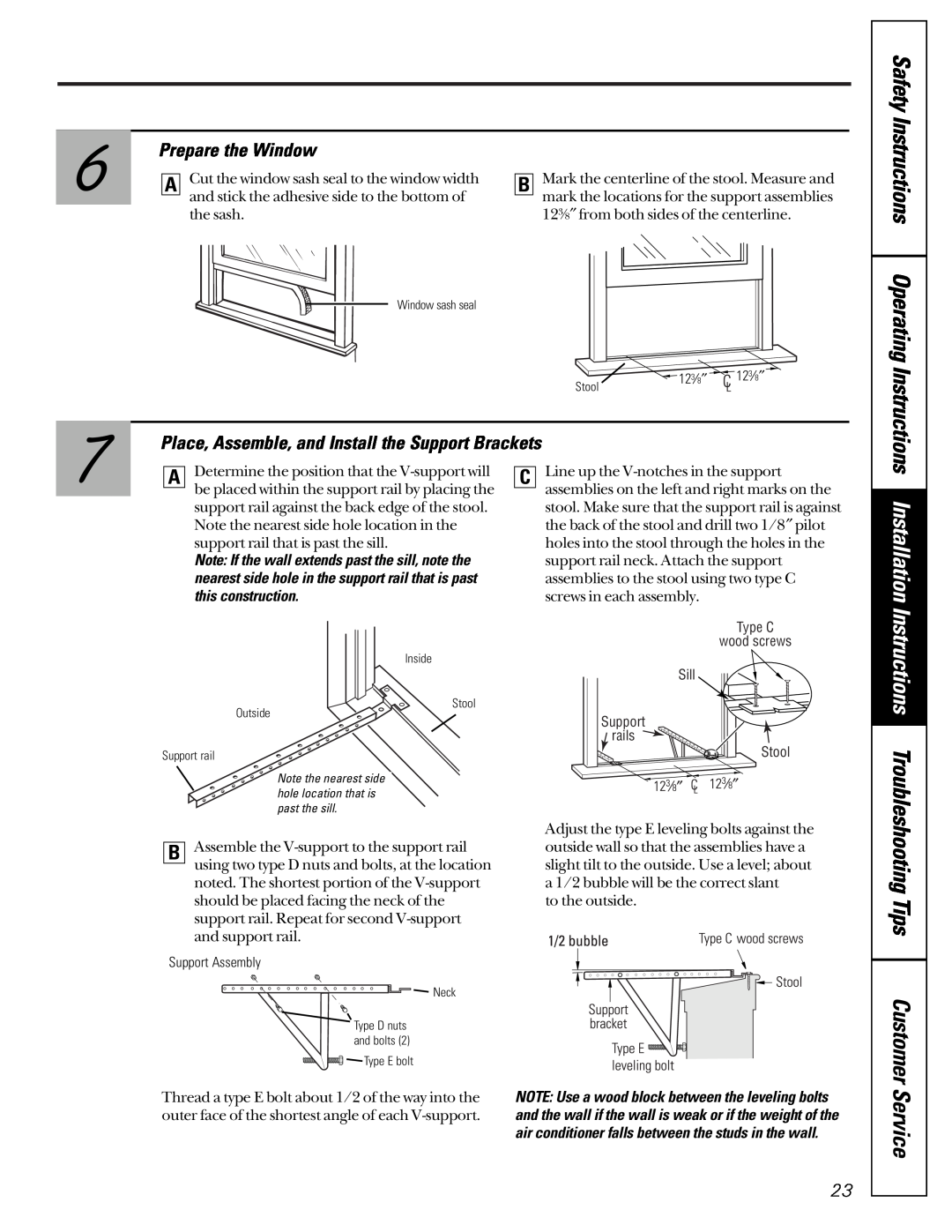
Prepare the Window
A | Cut the window sash seal to the window width | B | Mark the centerline of the stool. Measure and |
| and stick the adhesive side to the bottom of |
| mark the locations for the support assemblies |
|
| ||
| the sash. |
| 123⁄8″ from both sides of the centerline. |
Safety Instructions
7
Window sash seal
Stool
Place, Assemble, and Install the Support Brackets
123⁄8″ ![]() 123⁄8″
123⁄8″
Operating Instructions
ADetermine the position that the
Note: If the wall extends past the sill, note the nearest side hole in the support rail that is past this construction.
Inside
Stool
Outside
Support rail
C
Line up the
Type C
wood screws
Sill
Support
![]() rails
rails
Stool
Installation Instructions
Note the nearest side hole location that is past the sill.
BAssemble the
Support Assembly
![]()
![]() Neck
Neck
Type D nuts and bolts (2)
![]()
![]()
![]()
![]()
![]()
![]()
![]()
![]()
![]()
![]()
![]()
![]()
![]() Type E bolt
Type E bolt
Thread a type E bolt about 1/2 of the way into the outer face of the shortest angle of each
Adjust the type E leveling bolts against the outside wall so that the assemblies have a slight tilt to the outside. Use a level; about a 1/2 bubble will be the correct slant
to the outside.
NOTE: Use a wood block between the leveling bolts and the wall if the wall is weak or if the weight of the air conditioner falls between the studs in the wall.
Troubleshooting Tips
Customer Service
23