Advanced troubleshooting.
Manual Indexing for Each Regeneration
The control valve may be manually indexed to each regeneration position as follows:
1.Remove the control valve cover.
2.Press down on the top of the drive gear to disengage the cam gear. (See Step 1 in
3.With the cam gear disengaged, rotate the cam gear counterclockwise to the various positions, using the same steps as the
The control valve may also be operated in a fast mode for testing the control. To activate the fast mode, follow Steps 1 and 2 above to disengage the cam gear. When the cam gear is disengaged, it should be advanced slightly in a counterclockwise direction.
The switch will then activate the motor to cause the cam gear to advance through all the cycles in about 30 minutes. The control will not recognize a fast mode as a regeneration. Manual regenerations can be initiated only by pressing the manual regeneration switch on the face of the control.
Errors
This system continuously monitors itself and displays an error message if it detects something wrong.
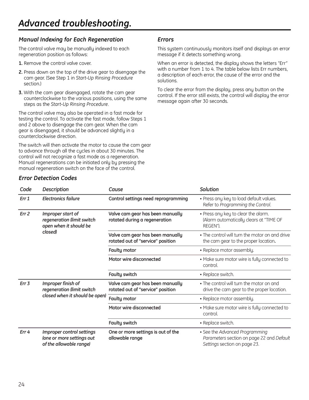
When an error is detected, the display shows the letters “Err” with a number from 1 to 4. The table below lists Err numbers, a description of each error, the cause of the error and the solutions.
To clear the error from the display, press any button on the control. If the error still exists, the control will display the error message again after 30 seconds.
Error Detection Codes
Code | Description | Cause | Solution |
Err 1 | Electronics failure | Control settings need reprogramming | • Press any key to load default values. |
|
|
| Refer to Programming the Control. |
Err 2 Improper start of regeneration (limit switch open when it should be closed)
Valve cam gear has been manually | • Press any key to clear the alarm. |
rotated during a regeneration | (Alarm automatically clears at “TIME OF |
| REGEN”). |
|
|
Valve cam gear has been manually | • The control will turn the motor on and drive |
rotated out of “service” position | the cam gear to the proper location. |
|
|
Faulty motor | • Replace motor assembly. |
|
|
Motor wire disconnected | • Make sure motor wire is fully connected to |
| control. |
Faulty switch | • Replace switch. |
Err 3 Improper finish of regeneration (limit switch closed when it should be open)
Valve cam gear has been manually | • The control will turn the motor on and |
rotated out of “service” position | drive the cam gear to the proper location. |
|
|
Faulty motor | • Replace motor assembly. |
|
|
Motor wire disconnected | • Make sure motor wire is fully connected to |
| control. |
Faulty switch | • Replace switch. |
Err 4 Improper control settings (one or more settings out of the allowable range)
One or more settings is out of the allowable range
•See the Advanced Programming Parameters section on page 22 and Default Settings section on page 23.
24
