Installation instructions.
Typical Installation Illustration
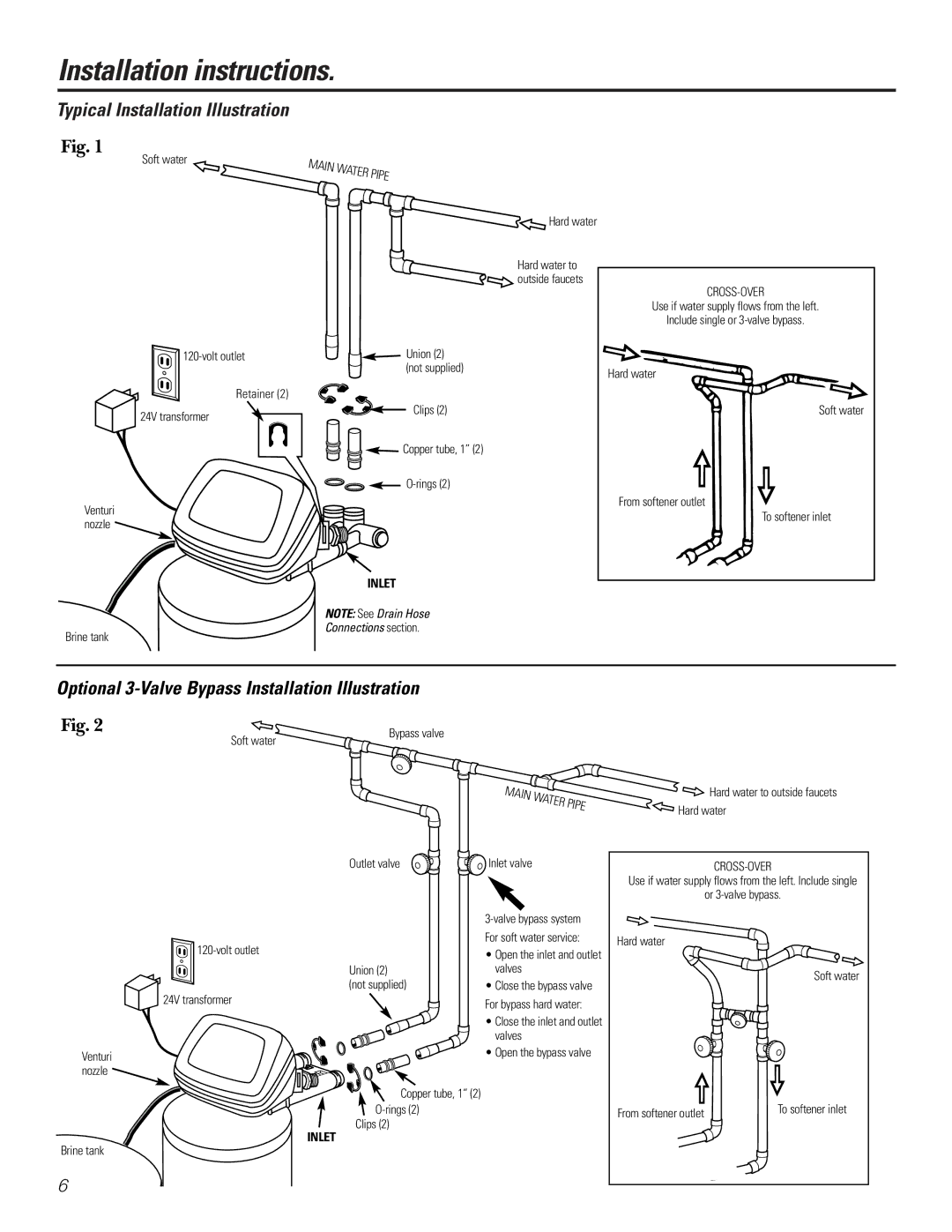
Fig. 1
Soft water
MAIN WATER PIPE
Retainer (2)
24V transformer
Venturi nozzle ![]()
Brine tank
![]() Hard water
Hard water
Hard water to ![]()
![]() outside faucets
outside faucets
![]()
![]() Union (2) (not supplied)
Union (2) (not supplied)
Clips (2)
![]()
![]()
![]() Copper tube, 1” (2)
Copper tube, 1” (2)
INLET
NOTE: See Drain Hose
Connections section.
CROSS-OVER
Use if water supply flows from the left.
Include single or
Hard water
Soft water
From softener outlet
To softener inlet
Optional 3-Valve Bypass Installation Illustration
Fig. 2 | Soft water | Bypass valve |
| ||
|
|
MAIN WATER PIPE
![]() Hard water to outside faucets
Hard water to outside faucets ![]() Hard water
Hard water
24V transformer
Venturi nozzle ![]()
INLET
Brine tank
6
Outlet valve | Inlet valve |
| |
| For soft water service: |
| • Open the inlet and outlet |
Union (2) | valves |
(not supplied) | • Close the bypass valve |
| For bypass hard water: |
| • Close the inlet and outlet |
| valves |
| • Open the bypass valve |
Copper tube, 1” (2) |
|
| |
Clips (2) |
|
Use if water supply flows from the left. Include single
or
Hard water
Soft water
|
| To softener inlet | |
From softener outlet | |||
|
|