Installation Instructions
FEED WATER SUPPLY
Check and comply with local plumbing codes as you plan, then install a cold feed water supply fitting.
A. PREFERRED INSTALLATION
1.Close the cold water supply valve under the sink.
2.Unscrew the flexible tubing from the supply valve that connects to the COLD water riser.
3.Install the feed water adapter* that is the diameter to match either the 1/2″ or 3/8″ plumbing in your location. DO NOT
OVERTIGHTEN.
*Notice the direction of the feed water adapter and coupling. It is installed
differently in order to match either the 1/2″ or 3/8″ plumbing in your location.
|
|
|
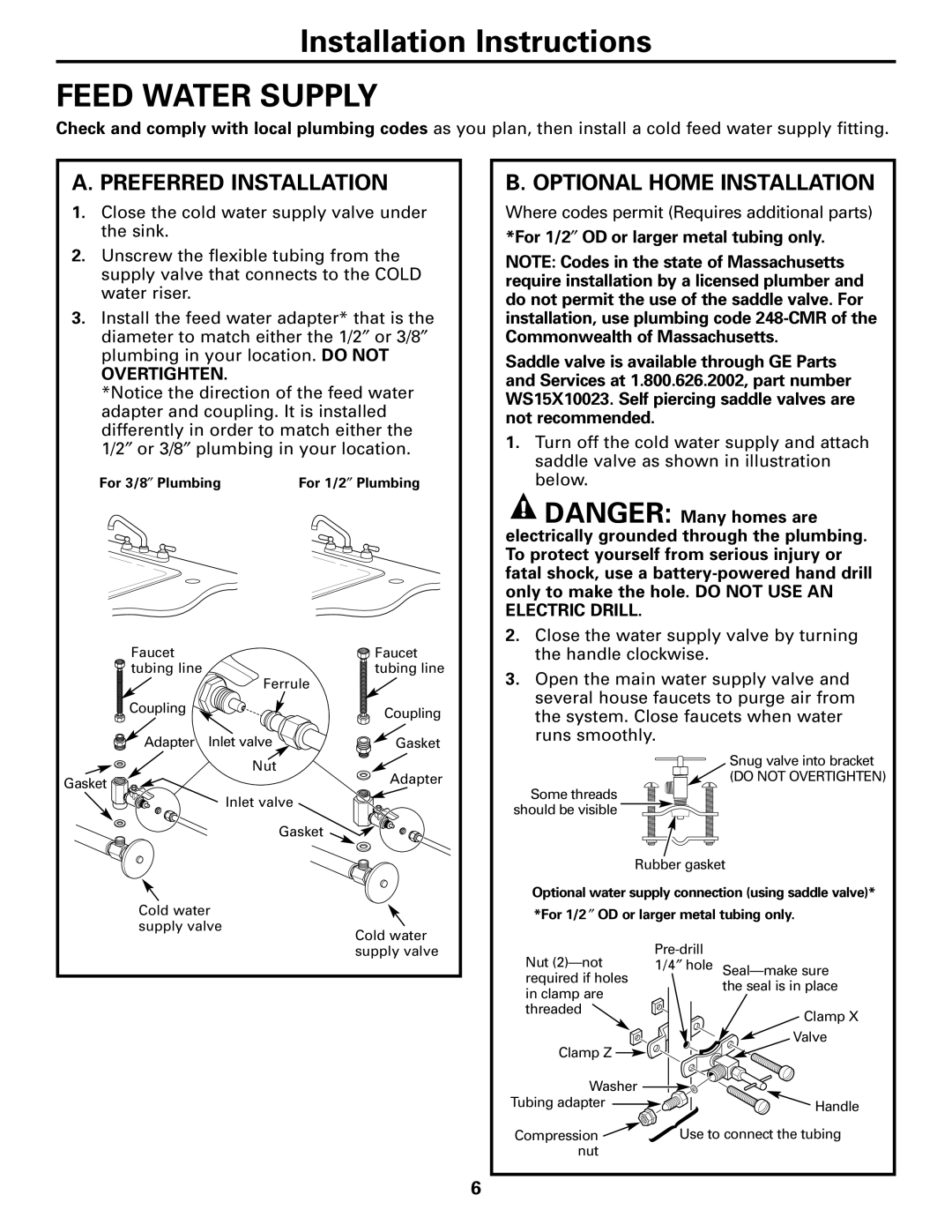
For 3/8″ Plumbing | For 1/2″ Plumbing | |
|
|
|
B. OPTIONAL HOME INSTALLATION
Where codes permit (Requires additional parts)
*For 1/2″ OD or larger metal tubing only.
NOTE: Codes in the state of Massachusetts require installation by a licensed plumber and do not permit the use of the saddle valve. For installation, use plumbing code
Saddle valve is available through GE Parts and Services at 1.800.626.2002, part number WS15X10023. Self piercing saddle valves are not recommended.
1.Turn off the cold water supply and attach saddle valve as shown in illustration below.
![]() DANGER: Many homes are electrically grounded through the plumbing. To protect yourself from serious injury or fatal shock, use a
DANGER: Many homes are electrically grounded through the plumbing. To protect yourself from serious injury or fatal shock, use a
Faucet ![]()
![]()
![]() tubing line
tubing line
Ferrule
![]() Coupling
Coupling
Adapter Inlet valve ![]()
![]()
![]()
![]()
![]() Nut Gasket
Nut Gasket ![]()
![]()
![]()
Inlet valve
Gasket
Faucet |
tubing line |
Coupling
Gasket
Adapter
2.Close the water supply valve by turning the handle clockwise.
3.Open the main water supply valve and several house faucets to purge air from the system. Close faucets when water runs smoothly.
Snug valve into bracket
(DO NOT OVERTIGHTEN)
Some threads should be visible
Rubber gasket
Optional water supply connection (using saddle valve)*
Cold water
supply valve
Cold water supply valve
*For 1/2 ″ OD or larger metal tubing only.
Nut | ||
1/4″ hole | ||
required if holes | the seal is in place | |
in clamp are | ||
| ||
threaded | Clamp X | |
| ||
Clamp Z | Valve | |
| ||
Washer |
| |
Tubing adapter | Handle | |
Compression | Use to connect the tubing | |
nut |
|
6