Filtration Drain Connection Installations

Check and comply with all state and local plumbing codes as you plan.

CAUTION: The options detailed below are the ONLY approved installation configurations. Do not use any drain saddle device.

NOTE: Failure to follow these Installation Instructions will void the Warranty, and the Installer will be responsible for any service, repair or damages caused thereby.

Safety Instructions

Preferred Installation Options

(Options A, B and C)

OPTION A.

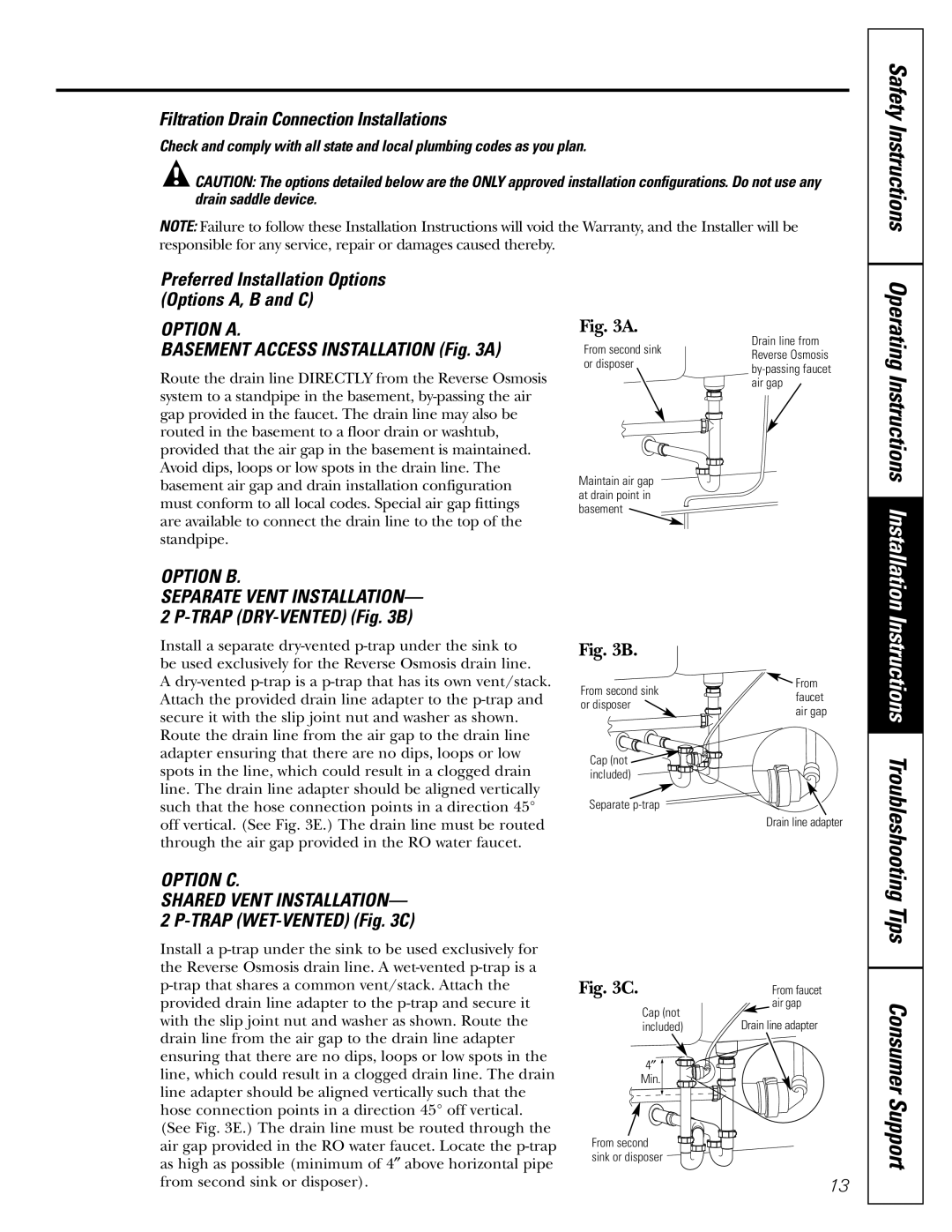
BASEMENT ACCESS INSTALLATION (Fig. 3A)

Route the drain line DIRECTLY from the Reverse Osmosis system to a standpipe in the basement, by-passing the air gap provided in the faucet. The drain line may also be routed in the basement to a floor drain or washtub, provided that the air gap in the basement is maintained. Avoid dips, loops or low spots in the drain line. The basement air gap and drain installation configuration must conform to all local codes. Special air gap fittings are available to connect the drain line to the top of the standpipe.

Fig. 3A.

From second sink or disposer

Maintain air gap at drain point in basement

Drain line from Reverse Osmosis by-passing faucet air gap

Operating Instructions Installation

OPTION B.

SEPARATE VENT INSTALLATION— 2 P-TRAP (DRY-VENTED) (Fig. 3B)

Install a separate dry-vented p-trap under the sink to be used exclusively for the Reverse Osmosis drain line.

A dry-vented p-trap is a p-trap that has its own vent/stack. Attach the provided drain line adapter to the p-trap and secure it with the slip joint nut and washer as shown. Route the drain line from the air gap to the drain line adapter ensuring that there are no dips, loops or low spots in the line, which could result in a clogged drain line. The drain line adapter should be aligned vertically such that the hose connection points in a direction 45° off vertical. (See Fig. 3E.) The drain line must be routed through the air gap provided in the RO water faucet.

Fig. 3B.

From second sink

From

faucet

or disposer

air gap


Cap (not

included)

Separate p-trap Drain line adapter

Instructions Troubleshooting

OPTION C.

SHARED VENT INSTALLATION— 2 P-TRAP (WET-VENTED) (Fig. 3C)

Install a p-trap under the sink to be used exclusively for the Reverse Osmosis drain line. A wet-vented p-trap is a p-trap that shares a common vent/stack. Attach the provided drain line adapter to the p-trap and secure it with the slip joint nut and washer as shown. Route the drain line from the air gap to the drain line adapter ensuring that there are no dips, loops or low spots in the line, which could result in a clogged drain line. The drain line adapter should be aligned vertically such that the hose connection points in a direction 45° off vertical. (See Fig. 3E.) The drain line must be routed through the air gap provided in the RO water faucet. Locate the p-trap as high as possible (minimum of 4″ above horizontal pipe from second sink or disposer).

Fig. 3C.

From faucet

Cap (not

air gap

Drain line adapter

included)

4


Min.


From second


sink or disposer


13

Tips Consumer Support

Page 13
Image 13
GE GXRV10ABL01 owner manual Safety Instructions, Tips Consumer Support, Filtration Drain Connection Installations

GXRV10ABL01 specifications

The GE GXRV10ABL01 is a sophisticated variable frequency drive (VFD) designed to enhance efficiency in various industrial applications. Characterized by its versatility and advanced technologies, this device is ideal for controlling the speed and torque of electric motors, making it an integral component for modern automation systems.

One of the most notable features of the GE GXRV10ABL01 is its compact design, which allows for easy integration into existing systems without requiring significant modifications. This space-saving characteristic makes it suitable for a range of environments, including manufacturing floors, processing plants, and HVAC systems.

The GXRV10ABL01 is equipped with cutting-edge control technologies that improve performance and energy efficiency. It utilizes advanced algorithms for precise motor control, enabling smooth acceleration and deceleration while minimizing energy consumption. This enhances the overall efficiency of processes such as pumping, fans, and conveyors.

Another key feature is its robust communication capabilities. The GXRV10ABL01 supports a variety of communication protocols, including Ethernet/IP, Modbus, and Profinet. This interoperability allows for seamless integration with other control systems and facilitates real-time monitoring and data exchange, supporting Industry 4.0 initiatives.

User-friendly programming and operation are facilitated by the drive's intuitive interface. The built-in keypad allows for straightforward configuration and adjustments, while the ability to connect to external displays enhances usability. Furthermore, the drive supports various programming options, enabling customization to meet specific application requirements.

Safety features are paramount in the design of the GE GXRV10ABL01. It comes equipped with built-in protection mechanisms, including overcurrent, overvoltage, and thermal overload protection. These safety measures help to prevent damage to both the drive and connected machinery, ensuring reliable operation and longevity.

Durability is another hallmark of the GXRV10ABL01. Its rugged construction and high-quality components make it resilient against harsh environments, withstanding fluctuations in temperature, dust, and moisture. This makes it a dependable choice for diverse industrial applications.

In summary, the GE GXRV10ABL01 is a state-of-the-art variable frequency drive that combines advanced control technologies, robust communication capabilities, and essential safety features. Its compact design, user-friendly interface, and durability ensure it meets the demands of modern industrial automation, providing greater efficiency and reliability for critical operations.