CONVERTING TO LP GAS (Standard Twin Burner models only)
or Converting Back to Natural Gas from LP
6 CHECK FOR LEAKS
When all connections have been made, make sure all range controls are in the off position and turn on the main gas supply valve. Use a liquid leak detector at all joints and connections to check for leaks in the system.
CAUTION: DO NOT USE A FLAME TO CHECK FOR GAS LEAKS.
When using test pressures greater than 1/2 psig to pressure test the gas supply system of the residence, disconnect the range and individual
7 ADJUST LOW FLAME SETTING
1.Light the top burners and continue turning all of the surface knobs to LOW.
2.Remove all 4 knobs.
3.With a small flat
blade screwdriver, turn the valve set screws clockwise to decrease
flame size, counterclockwise to increase flame size. Adjust until the flame is about the same height as the top of the burner.
4.Replace the knobs.
5.Check for flame outage by opening and closing the oven door several times. If the flame goes out, increase the flame size.
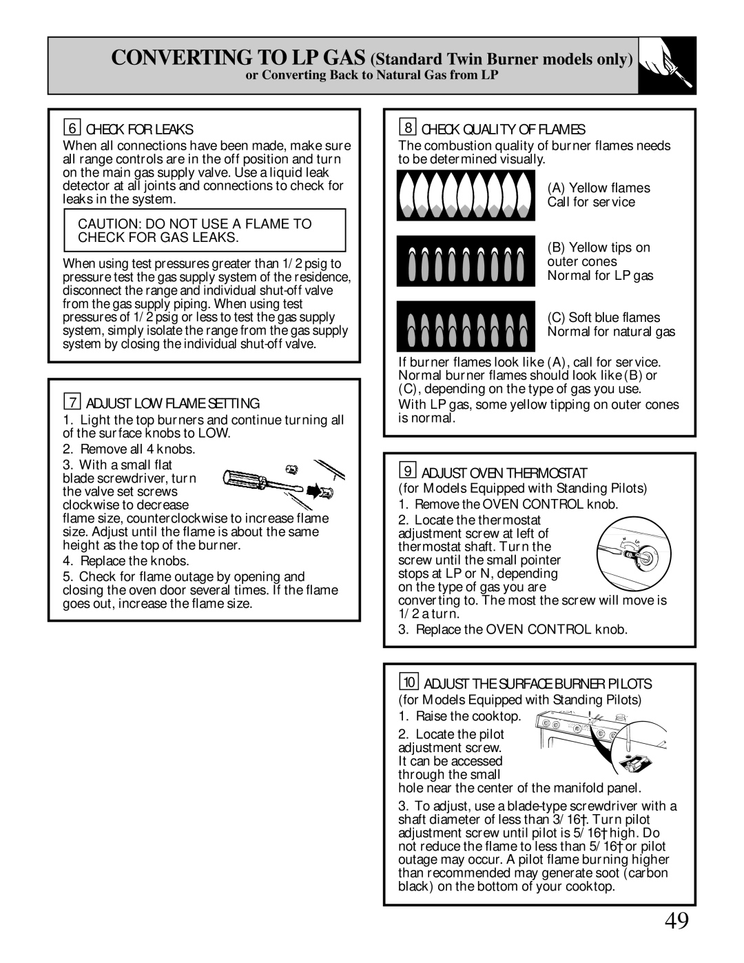
8 CHECK QUALITY OF FLAMES
The combustion quality of burner flames needs to be determined visually.
(A) Yellow flames—
Call for service
(B) Yellow tips on outer cones— Normal for LP gas
(C) Soft blue flames—
Normal for natural gas
If burner flames look like (A), call for service. Normal burner flames should look like (B) or (C), depending on the type of gas you use.
With LP gas, some yellow tipping on outer cones is normal.
9 ADJUST OVEN THERMOSTAT
(for Models Equipped with Standing Pilots)
1.Remove the OVEN CONTROL knob.
2.Locate the thermostat
adjustment screw at left of thermostat shaft. Turn the screw until the small pointer stops at LP or N, depending
on the type of gas you are
converting to. The most the screw will move is 1/2 a turn.
3.Replace the OVEN CONTROL knob.
10 ADJUST THE SURFACE BURNER PILOTS
(for Models Equipped with Standing Pilots)
1. Raise the cooktop.
2. Locate the pilot adjustment screw. It can be accessed through the small
hole near the center of the manifold panel.
3.To adjust, use a
49