14
PB3-POS-RP ProBridge
User Manual
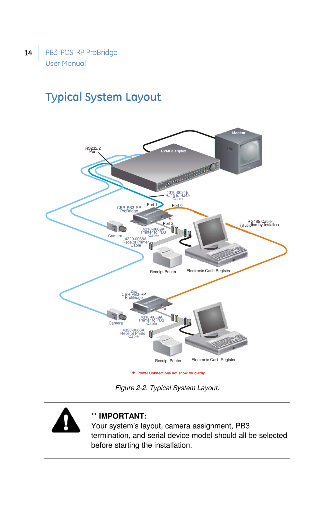
Typical System Layout
RS232/2
Port
Monitor
DVMRe Triplex
| Port 1 | Port 0 |
|
| |
ProBridge |
|
|
Port*2 | RS485 Cable |
(Supplied by Installer) |
Printer to PB3
Camera
Receipt Printer
Cable
Receipt Printer Electronic Cash Register
2nd
ProBridge
*
Printer to PB3
CameraCable
Receipt Printer
Cable
Receipt Printer Electronic Cash Register
*Power Connections not show for clarity.
Figure 2-2. Typical System Layout.
**IMPORTANT:
Your system’s layout, camera assignment, PB3 termination, and serial device model should all be selected before starting the installation.