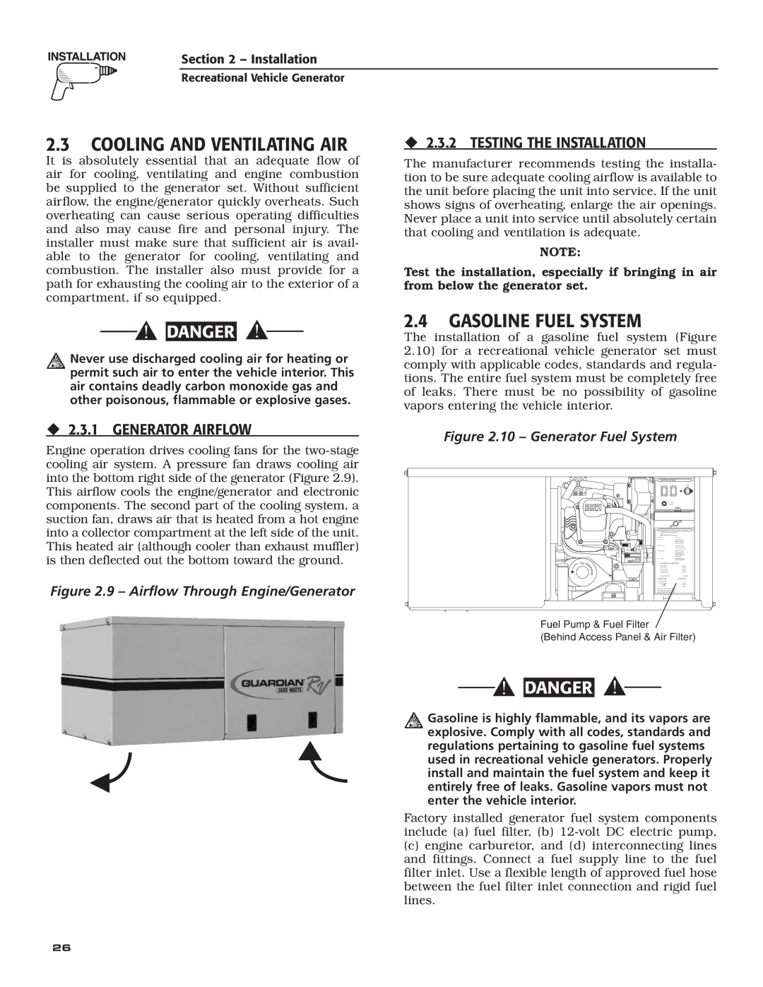
004700-00 specifications
Generac Power Systems is a recognized leader in the field of backup power generation, and one of its standout products is the Generac 004700-00. This reliable and high-performance generator has garnered attention for its robust features and advanced technological capabilities, making it an appealing choice for homeowners and businesses alike.One of the key features of the Generac 004700-00 is its ability to deliver a reliable source of power during outages. With a powerful engine, this generator is designed to handle substantial loads, including sensitive electronics, heating systems, and appliances without compromising performance. The generator achieves this with a recommended horsepower rating that ensures a steady output even under heavy demand.
Incorporating Generac’s advanced Synch Power technology, the 004700-00 enables users to operate multiple devices simultaneously without any disruption. This feature ensures that the power provided is stable and consistent, minimizing the risk of damage to electronic devices during surges or fluctuations. Furthermore, the generator is engineered with a user-friendly control panel, making it easy to monitor performance metrics and adjust settings as necessary.
A standout characteristic of the 004700-00 is its quiet operation. Unlike many traditional generators, this unit utilizes noise-reducing technologies, ensuring that it operates at a lower decibel level. This feature is particularly beneficial for residential areas, where noise restrictions may be a concern.
The Generac 004700-00 also excels in fuel efficiency, allowing it to run longer on less fuel. This is achieved through its advanced engine design and efficient fuel consumption rate, which not only saves on operating costs but also reduces the environmental impact. Additionally, the generator is compatible with various fuel types, enhancing its versatility and convenience for users.
Ease of maintenance is another consideration with the 004700-00, as it is equipped with a maintenance alert system that notifies users when service is required. This proactive approach to care ensures that the generator remains in optimal working condition, prolonging its lifespan and reliability.
In summary, the Generac Power Systems 004700-00 stands out with its powerful performance, advanced technology, quiet operation, fuel efficiency, and user-friendly features. Whether for residential or commercial use, this generator provides a dependable solution for anyone in need of backup power when it matters most.

