Section 3 - Operation
Guardian 40kW
Make sure the generator battery is fully charged, prop- erly installed and interconnected, and ready for use.
Check to ensure that there are no loose electrical con- nections. Restrain any loose wires to keep them clear of any moving generator set components.
3.2CONTROL CONSOLE
COMPONENTS
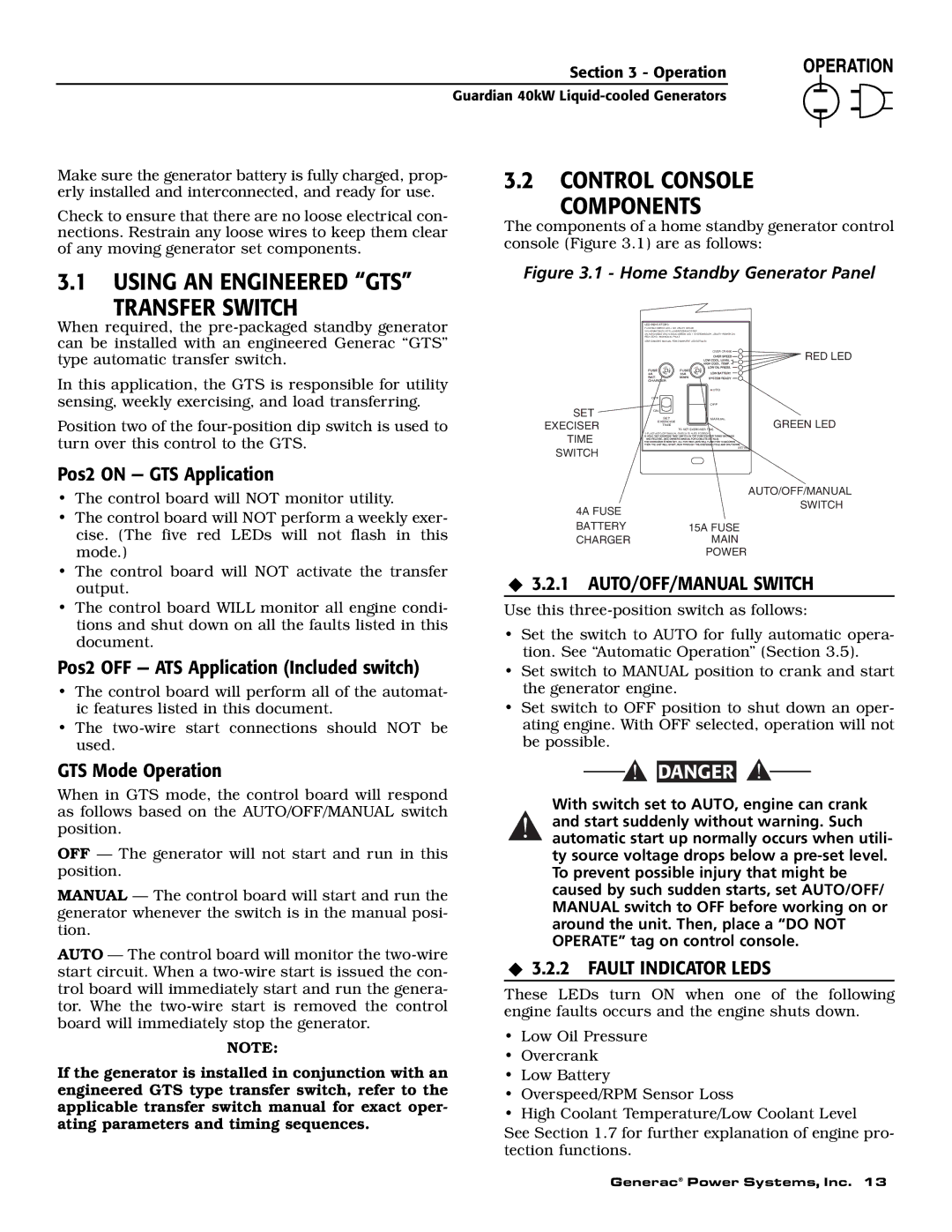
The components of a home standby generator control console (Figure 3.1) are as follows:
3.1USING AN ENGINEERED “GTS”
TRANSFER SWITCH
Figure 3.1 - Home Standby Generator Panel
When required, the
In this application, the GTS is responsible for utility sensing, weekly exercising, and load transferring.
Position two of the
Pos2 ON — GTS Application
SET EXECISER TIME SWITCH
LED INDICATORS:
FLASHING GREEN LED = NO UTILITY SENSE
5 FLASHING RED LED'S = EXERCISER NOT SET
(IN AUTO MODE ONLY) SOLID GREEN LED = SYSTEM READY, UTILITY POWER ON RED LED'S = INDIVIDUAL FAULT
(SEE OWNER'S MANUAL FOR COMPLETE LED DETAILS)
| OVER CRANK | RED LED |
|
| |
SE F | SE |
|
| AUTO |
|
OFF |
|
|
| OFF |
|
ON |
|
|
SET | MANUAL | GREEN LED |
EXERCISE | TO SET EXERCISER TIME |
TIME
1) PLACE AUTO/OFF/MANUAL SWITCH TO AUTO POSITION.
0E7194
•The control board will NOT monitor utility.
•The control board will NOT perform a weekly exer- cise. (The five red LEDs will not flash in this mode.)
•The control board will NOT activate the transfer output.
•The control board WILL monitor all engine condi- tions and shut down on all the faults listed in this document.
Pos2 OFF — ATS Application (Included switch)
•The control board will perform all of the automat- ic features listed in this document.
•The
GTS Mode Operation
When in GTS mode, the control board will respond as follows based on the AUTO/OFF/MANUAL switch position.
OFF — The generator will not start and run in this position.
MANUAL — The control board will start and run the generator whenever the switch is in the manual posi- tion.
AUTO — The control board will monitor the
NOTE:
If the generator is installed in conjunction with an engineered GTS type transfer switch, refer to the applicable transfer switch manual for exact oper- ating parameters and timing sequences.
| AUTO/OFF/MANUAL |
4A FUSE | SWITCH |
| |
BATTERY | 15A FUSE |
CHARGER | MAIN |
| POWER |
3.2.1 AUTO/OFF/MANUAL SWITCH
Use this
•Set the switch to AUTO for fully automatic opera- tion. See “Automatic Operation” (Section 3.5).
•Set switch to MANUAL position to crank and start the generator engine.
•Set switch to OFF position to shut down an oper- ating engine. With OFF selected, operation will not be possible.
![]()
![]() DANGER
DANGER
With switch set to AUTO, engine can crank
!and start suddenly without warning. Such automatic start up normally occurs when utili- ty source voltage drops below a
3.2.2 FAULT INDICATOR LEDS
These LEDs turn ON when one of the following engine faults occurs and the engine shuts down.
•Low Oil Pressure
•Overcrank
•Low Battery
•Overspeed/RPM Sensor Loss
•High Coolant Temperature/Low Coolant Level
See Section 1.7 for further explanation of engine pro- tection functions.
Generac® Power Systems, Inc. 13