COMFORTNET™ SYSTEM

NON-COMM (APPLIES ONLY TO A CT COMPATIBLE FURNACE MATCHED

WITH A NON-CT COMPATIBLE SINGLE STAGE AIR CONDITIONER)

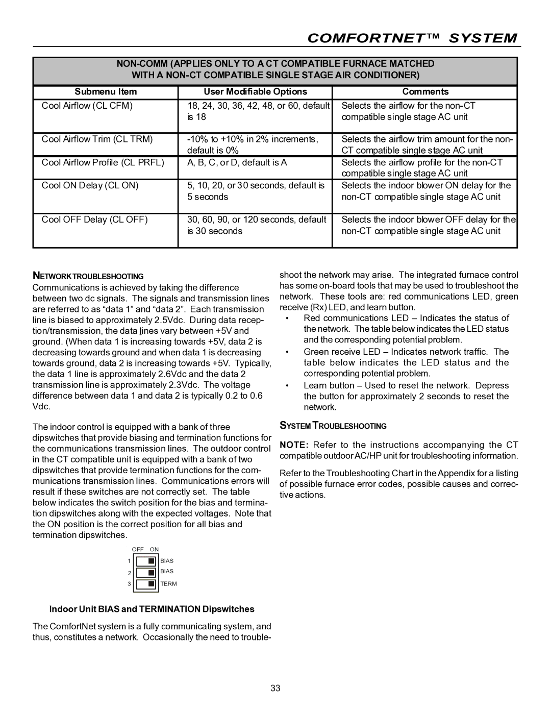
Submenu Item

User Modifiable Options

Comments

Cool Airflow (CL CFM)

18, 24, 30, 36, 42, 48, or 60, default

Selects the airflow for the non-CT


is 18

compatible single stage AC unit


Cool Airflow Trim (CL TRM)

-10% to +10% in 2% increments,

Selects the airflow trim amount for the non-


default is 0%

CT compatible single stage AC unit

Cool Airflow Profile (CL PRFL)

A, B, C, or D, default is A

Selects the airflow profile for the non-CT


compatible single stage AC unit

Cool ON Delay (CL ON)

5, 10, 20, or 30 seconds, default is

Selects the indoor blower ON delay for the


5 seconds

non-CT compatible single stage AC unit


Cool OFF Delay (CL OFF)

30, 60, 90, or 120 seconds, default

Selects the indoor blower OFF delay for the


is 30 seconds

non-CT compatible single stage AC unit


NETWORKTROUBLESHOOTING

Communications is achieved by taking the difference between two dc signals. The signals and transmission lines are referred to as “data 1” and “data 2”. Each transmission line is biased to approximately 2.5Vdc. During data recep- tion/transmission, the data lines vary between +5V and ground. (When data 1 is increasing towards +5V, data 2 is decreasing towards ground and when data 1 is decreasing towards ground, data 2 is increasing towards +5V. Typically, the data 1 line is approximately 2.6Vdc and the data 2 transmission line is approximately 2.3Vdc. The voltage difference between data 1 and data 2 is typically 0.2 to 0.6 Vdc.

The indoor control is equipped with a bank of three dipswitches that provide biasing and termination functions for the communications transmission lines. The outdoor control in the CT compatible unit is equipped with a bank of two dipswitches that provide termination functions for the com- munications transmission lines. Communications errors will result if these switches are not correctly set. The table below indicates the switch position for the bias and termina- tion dipswitches along with the expected voltages. Note that the ON position is the correct position for all bias and termination dipswitches.

OFF

ON

1


BIAS


2


BIAS


3


TERM


shoot the network may arise. The integrated furnace control has some on-board tools that may be used to troubleshoot the network. These tools are: red communications LED, green receive (Rx) LED, and learn button.

Red communications LED – Indicates the status of the network. The table below indicates the LED status and the corresponding potential problem.

Green receive LED – Indicates network traffic. The table below indicates the LED status and the corresponding potential problem.

Learn button – Used to reset the network. Depress the button for approximately 2 seconds to reset the network.

SYSTEM TROUBLESHOOTING

NOTE: Refer to the instructions accompanying the CT compatible outdoor AC/HP unit for troubleshooting information.

Refer to the Troubleshooting Chart in the Appendix for a listing of possible furnace error codes, possible causes and correc- tive actions.

Indoor Unit BIAS and TERMINATION Dipswitches

The ComfortNet system is a fully communicating system, and thus, constitutes a network. Occasionally the need to trouble-

33

Page 33
Image 33
Goodman Mfg VC8 instruction manual Cool Airflow CL CFM

VC8 specifications

Goodman Manufacturing has established itself as a leading provider of quality heating, ventilation, and air conditioning (HVAC) systems. Among its impressive lineup is the Goodman VC8, a versatile and efficient variable-capacity air conditioner that stands out due to its innovative design and advanced technologies.

The Goodman VC8 is known for its superior energy efficiency, featuring a SEER (Seasonal Energy Efficiency Ratio) rating higher than 20. This means that it operates efficiently across various climatic conditions, ensuring optimal cooling with minimal energy consumption. The high SEER rating not only translates to lower energy bills but also contributes to a reduced environmental footprint, making it a smart choice for eco-conscious consumers.

One of the standout features of the VC8 is its variable-speed compressor, which allows the system to adjust its output based on the cooling needs of the space. This technology enables the unit to run at lower speeds for longer periods, maintaining a consistent temperature while reducing energy usage. The variable-speed operation also contributes to quieter operation compared to traditional air conditioning systems. Homeowners can enjoy a peaceful indoor environment without the disruptive noise commonly associated with air conditioning units.

In terms of comfort, the Goodman VC8 employs advanced humidity control features, ensuring that moisture is efficiently managed within the space. This not only enhances comfort levels but also helps to prevent issues related to excessive humidity, such as mold growth and structural damage.

The VC8 is designed for reliable performance and durability, with its robust construction and dependable components. Goodman manufactures its products with high-quality materials to withstand the rigors of daily use and various weather conditions, ensuring long-lasting operation.

Additionally, the VC8 incorporates smart technology features, including compatibility with Wi-Fi-enabled thermostats. Homeowners can easily monitor and control their system remotely, providing convenience and peace of mind.

The Goodman VC8 is an exemplary solution for those looking for an energy-efficient, advanced air conditioning system. With its variable-speed compressor, excellent humidity control, durable construction, and smart features, it promises comfort and reliability suitable for any residential space. By choosing Goodman, homeowners can invest in a quality HVAC system designed to meet modern needs and preferences.