Installation
Fluid Inlet and Outlet Ports
NOTE: Remove and reverse the manifold(s) to change the orientation of inlet or outlet port(s). Follow Torque Instructions on page 16.
Aluminum (1050A)
The fluid inlet and outlet manifolds each have four 1 in. npt(f) or bspt threaded ports (FIG. 3, M, N). Close off the unused ports, using the supplied plugs.
Plastic (1050P, 1050C)
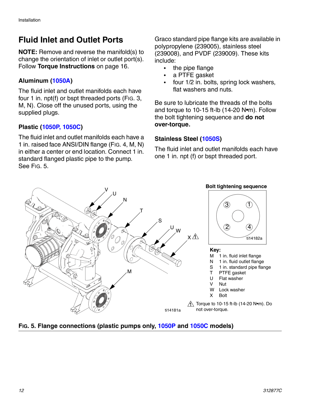
The fluid inlet and outlet manifolds each have a 1 in. raised face ANSI/DIN flange (FIG. 4, M, N) in either a center or end location. Connect 1 in. standard flanged plastic pipe to the pump.
See FIG. 5.
Graco standard pipe flange kits are available in polypropylene (239005), stainless steel (239008), and PVDF (239009). These kits include:
•the pipe flange
•a PTFE gasket
•four 1/2 in. bolts, spring lock washers, flat washers and nuts.
Be sure to lubricate the threads of the bolts and torque to
Stainless Steel (1050S)
The fluid inlet and outlet manifolds each have one 1 in. npt (f) or bspt threaded port.
V
U
N
T
S
U W
M
ti14181a
Bolt tightening sequence
3 1
2 4
X 1 | ti14182a |
Key:
M1 in. fluid inlet flange
N1 in. fluid outlet flange
S1 in. standard pipe flange
TPTFE gasket
UFlat washer
VNut
WLock washer
XBolt
1Torque to
FIG. 5. Flange connections (plastic pumps only, 1050P and 1050C models)
12 | 312877C |
