Installation
E F C BA
N
D
R
K L
J
G
M
ti14164a
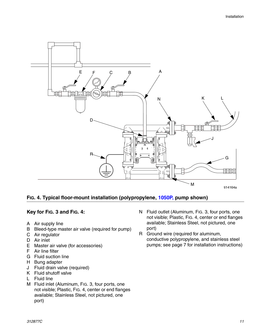
FIG. 4. Typical floor-mount installation (polypropylene, 1050P, pump shown)
Key for FIG. 3 and FIG. 4:
AAir supply line
B
CAir regulator
DAir inlet
EMaster air valve (for accessories)
FAir line filter
GFluid suction line
HBung adapter
JFluid drain valve (required)
KFluid shutoff valve
LFluid line
MFluid inlet (Aluminum, FIG. 3, four ports, one not visible; Plastic, FIG. 4, center or end flanges available; Stainless Steel, not pictured, one port)
NFluid outlet (Aluminum, FIG. 3, four ports, one not visible; Plastic, FIG. 4, center or end flanges available; Stainless Steel, not pictured, one
port)
RGround wire (required for aluminum, conductive polypropylene, and stainless steel pumps; see page 7 for installation instructions)
312877C | 11 |