Installation
|
|
|
|
| Key: | |
|
|
|
|
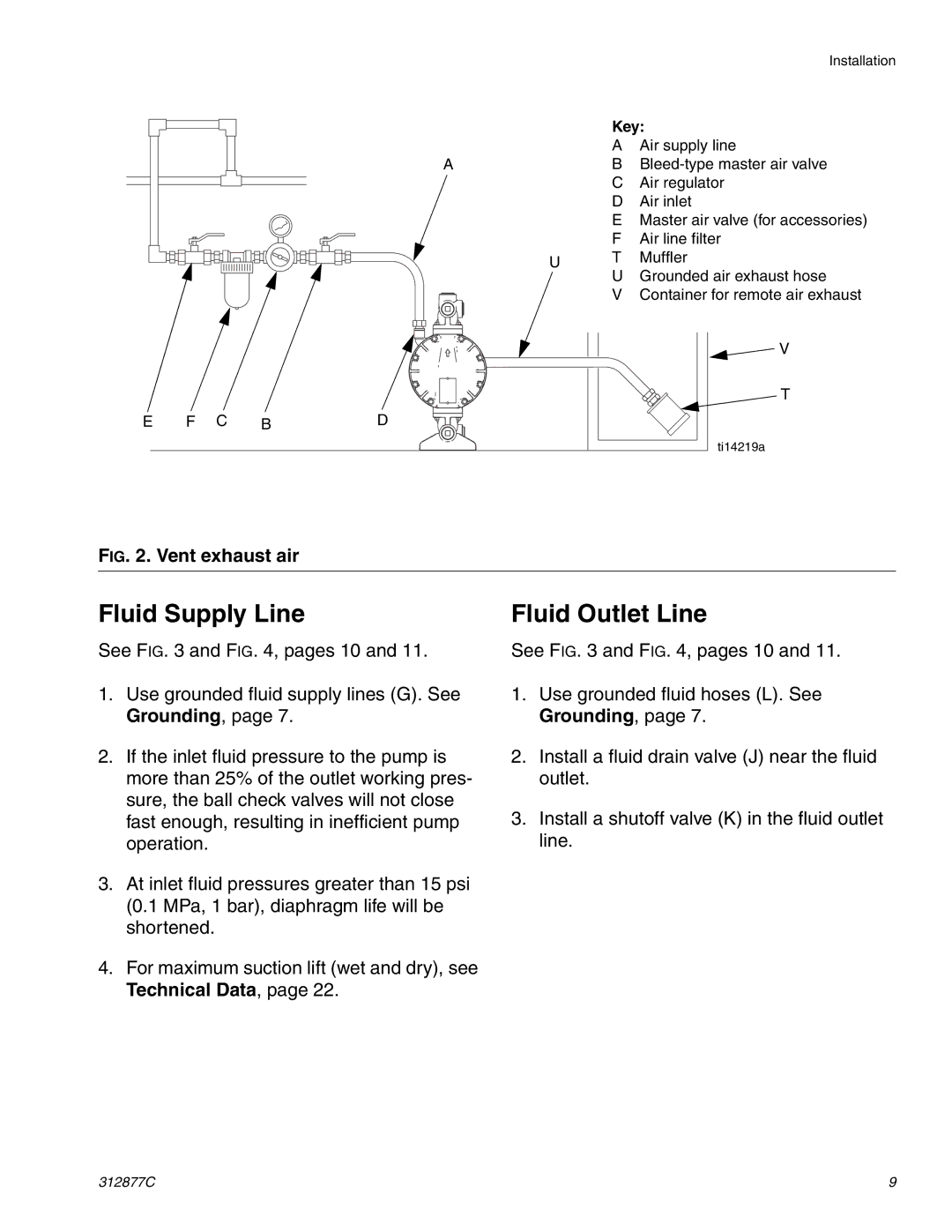
| A | Air supply line |
|
|
| A |
| B | |
|
|
|
|
| C | Air regulator |
|
|
|
|
| D | Air inlet |
|
|
|
|
| E Master air valve (for accessories) | |
|
|
|
|
| F | Air line filter |
|
|
|
| U | T | Muffler |
|
|
|
| U | Grounded air exhaust hose | |
|
|
|
|
| ||
|
|
|
|
| V Container for remote air exhaust | |
|
|
|
|
|
| V |
|
|
|
|
|
| T |
E | F C | B | D |
|
|
|
|
|
|
|
|
| ti14219a |
FIG. 2. Vent exhaust air
Fluid Supply Line
See FIG. 3 and FIG. 4, pages 10 and 11.
1.Use grounded fluid supply lines (G). See Grounding, page 7.
2.If the inlet fluid pressure to the pump is more than 25% of the outlet working pres- sure, the ball check valves will not close fast enough, resulting in inefficient pump operation.
3.At inlet fluid pressures greater than 15 psi (0.1 MPa, 1 bar), diaphragm life will be shortened.
4.For maximum suction lift (wet and dry), see Technical Data, page 22.
Fluid Outlet Line
See FIG. 3 and FIG. 4, pages 10 and 11.
1.Use grounded fluid hoses (L). See Grounding, page 7.
2.Install a fluid drain valve (J) near the fluid outlet.
3.Install a shutoff valve (K) in the fluid outlet line.
312877C | 9 |