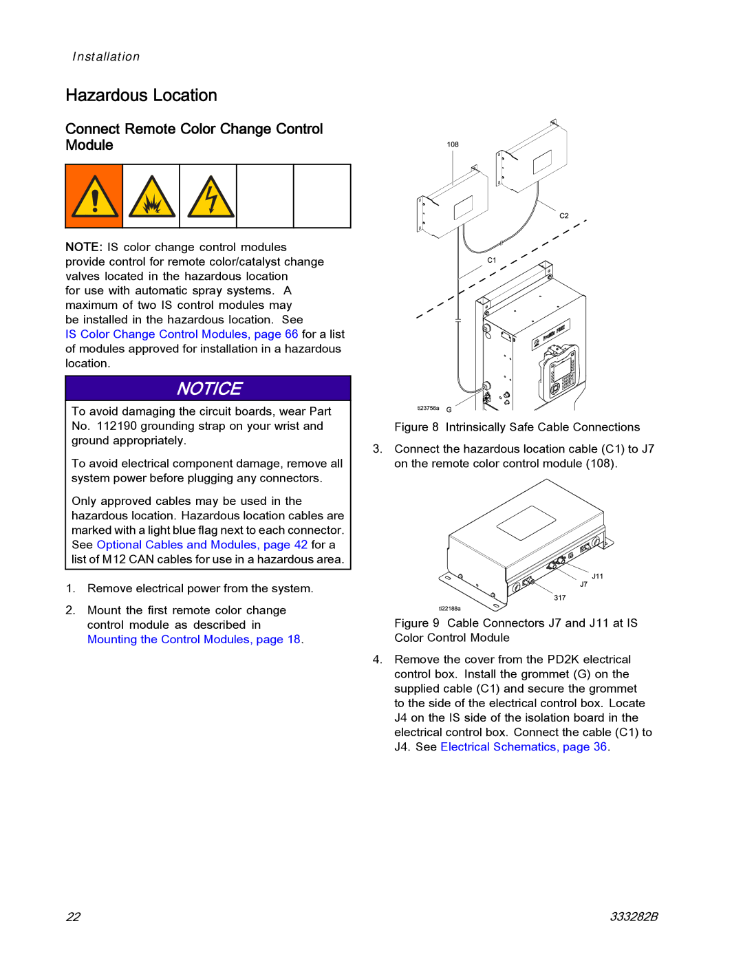
333282B specifications
The Graco 333282B is a high-performance airless paint sprayer, designed specifically for both DIY enthusiasts and professional painters who require efficiency and precision. This versatile sprayer is suitable for a variety of projects, including home renovations, commercial applications, and creative crafts.One of the standout features of the Graco 333282B is its robust TrueLife airless technology, which allows for a smooth and even finish without the hassles associated with traditional paintbrushes or rollers. This technology minimizes overspray while ensuring consistent paint delivery, making it an optimal choice for achieving professional-quality results.
In terms of power, the Graco 333282B incorporates a reliable electric motor that provides enough strength to handle thick materials, such as latex paints and stains. Its powerful motor ensures that users can cover large areas quickly, reducing the time spent on projects. Furthermore, the unit features an adjustable pressure control, allowing users to tailor the flow rate to their specific needs, which enhances versatility across various surfaces and types of paint.
The sprayer's design emphasizes user-friendliness. It is lightweight and portable, making it easy to transport and maneuver around different workspaces. The innovative design also incorporates an easy-to-clean tip, allowing for straightforward maintenance and ensuring longevity in performance. Additionally, the Graco 333282B is equipped with a flexible hose that accommodates movement without compromising pressure, making it easier to reach tight spaces and high walls.
Safety is also a priority, as the Graco 333282B features a built-in tip guard that protects users from accidental injuries when the sprayer is not in use. The unit is intentionally engineered for stability, minimizing the chances of tipping over during operation.
Overall, the Graco 333282B combines advanced technology, user-friendly features, and durability, making it an excellent choice for anyone looking to achieve exceptional painting results efficiently. Whether tackling large-scale projects or smaller DIY tasks, this sprayer delivers the performance necessary to get the job done right.

