Mounting Hole Layout
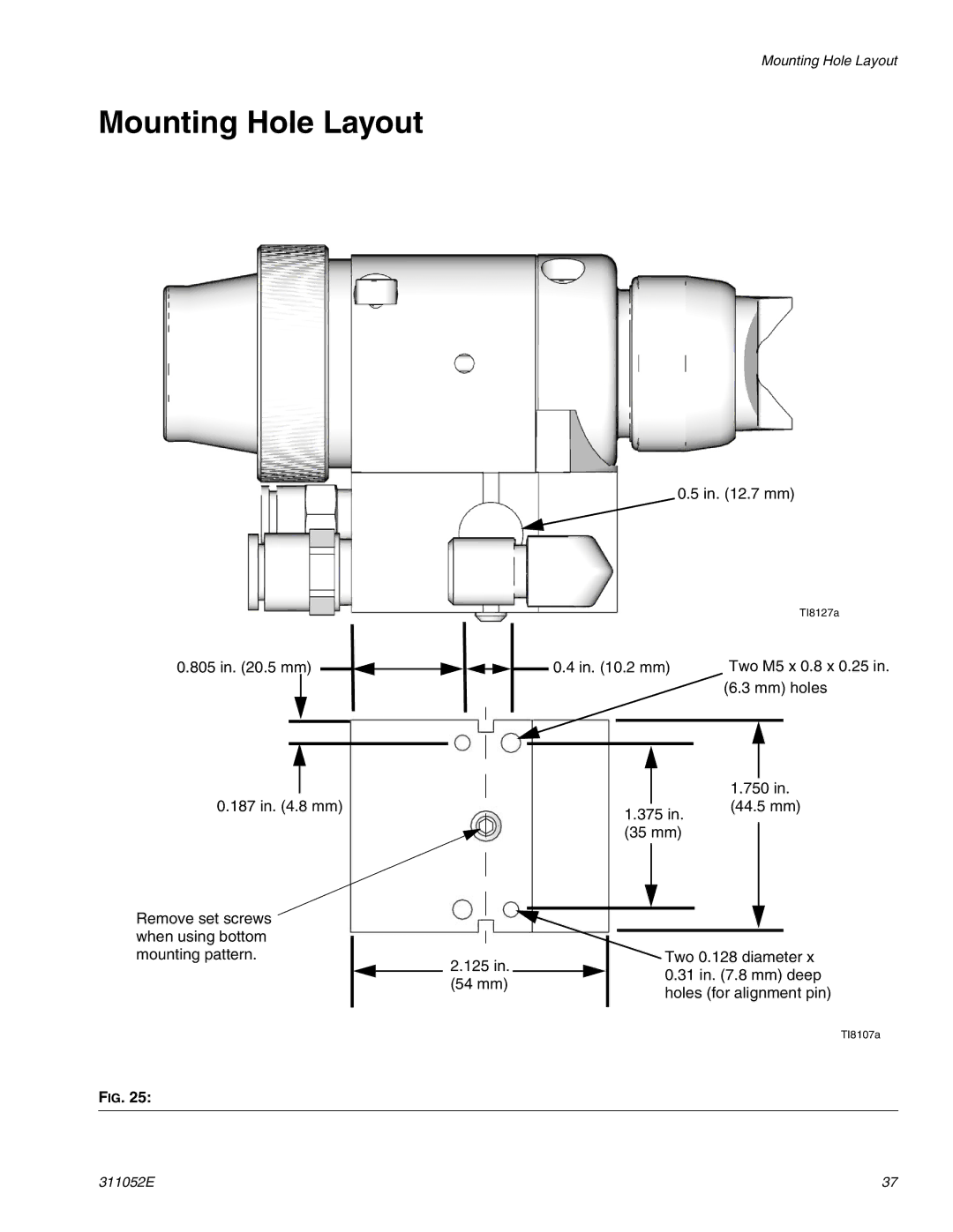
Mounting Hole Layout
0.5 in. (12.7 mm)
|
|
|
|
|
|
|
|
|
|
|
|
|
|
|
|
|
|
|
|
|
|
|
| TI8127a |
0.805 in. (20.5 mm) |
|
|
|
|
|
|
|
|
|
|
|
| 0.4 in. (10.2 mm) | Two M5 x 0.8 x 0.25 in. | ||||||||||
|
|
|
|
|
|
|
|
|
| |||||||||||||||
|
|
|
|
|
|
|
|
|
|
|
|
|
|
|
|
|
|
|
|
| (6.3 mm) holes | |||
|
|
|
|
|
|
|
|
|
|
|
|
|
|
|
|
|
|
|
|
|
|
|
|
|
|
|
|
|
|
|
|
|
|
|
|
|
|
|
|
|
|
|
|
|
|
|
|
|
|
|
|
|
|
|
|
|
|
|
|
|
|
|
|
|
|
|
|
|
|
|
|
|
|
|
|
|
|
|
|
|
|
|
|
|
|
|
|
|
|
|
|
|
|
|
|
|
|
|
|
|
|
|
|
|
|
|
|
|
|
|
|
|
|
|
|
|
|
|
|
|
|
|
|
|
|
|
|
|
|
|
|
|
|
|
|
|
|
|
|
|
|
|
|
|
|
|
|
|
|
|
|
|
|
|
|
|
|
|
|
|
|
|
|
|
|
|
|
|
|
|
|
|
|
|
|
|
|
|
|
|
|
|
|
|
|
|
|
|
|
|
|
|
|
|
|
|
|
|
|
0.187 in. (4.8 mm)
1.375 in.
(35 mm)
1.750 in.
(44.5 mm)
Remove set screws when using bottom
mounting pattern.
2.125 in. (54 mm)
Two 0.128 diameter x
0.31in. (7.8 mm) deep holes (for alignment pin)
TI8107a
FIG. 25:
311052E | 37 |