Installation
Connect Fluid Line
Before connecting the fluid line, blow it out with air and flush it with solvent. Use solvent that is compat- ible with the fluid to be sprayed.
A fluid drain valve(s) is required in your system to assist in relieving fluid pressure in the displacement pump, hose and gun; triggering the gun to relieve pressure may not be sufficient.
A fluid pressure regulator must be installed in the system if the pump's maximum working pressure exceeds the gun's maximum fluid working pressure (see the front cover).
1.Install a fluid filter and drain valve(s) close to the pump's fluid outlet.
2.Install a fluid pressure regulator to control fluid pres- sure to the gun.
Some applications require
3.Install a fluid shutoff valve to shut off the fluid supply to the gun.
4.Install an
5.In a circulating system, connect a grounded fluid supply hose to the gun fluid fitting. Connect a grounded return hose to the other port.
In a
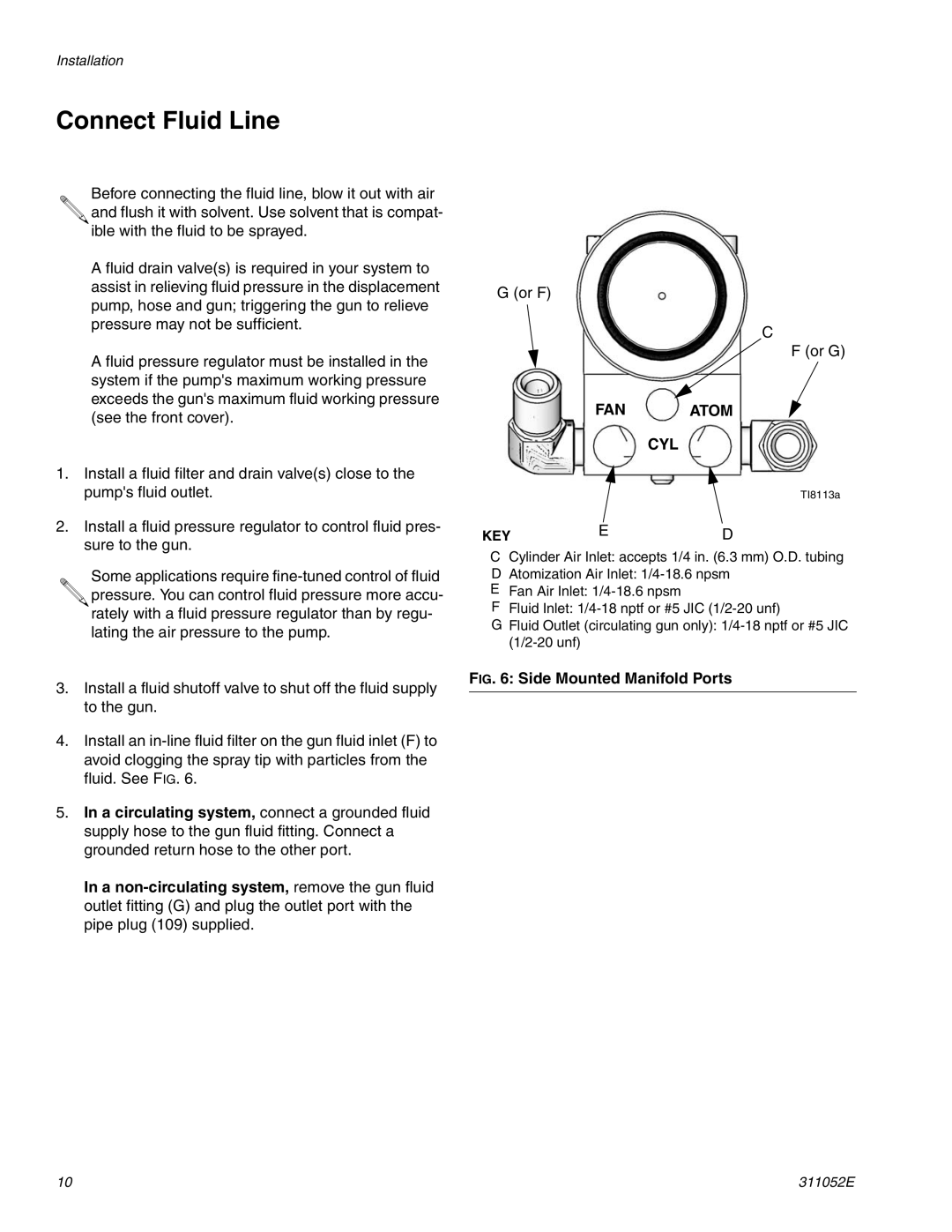
G (or F)
C
F (or G)
FAN ATOM
CYL
TI8113a
KEY | E | D |
CCylinder Air Inlet: accepts 1/4 in. (6.3 mm) O.D. tubing D Atomization Air Inlet:
E Fan Air Inlet:
F Fluid Inlet:
G Fluid Outlet (circulating gun only):
FIG. 6: Side Mounted Manifold Ports
10 | 311052E |