Manuals
/
Greenheck Fan
/
Household Appliance
/
Electric Heater
Greenheck Fan
Part #470655
manual
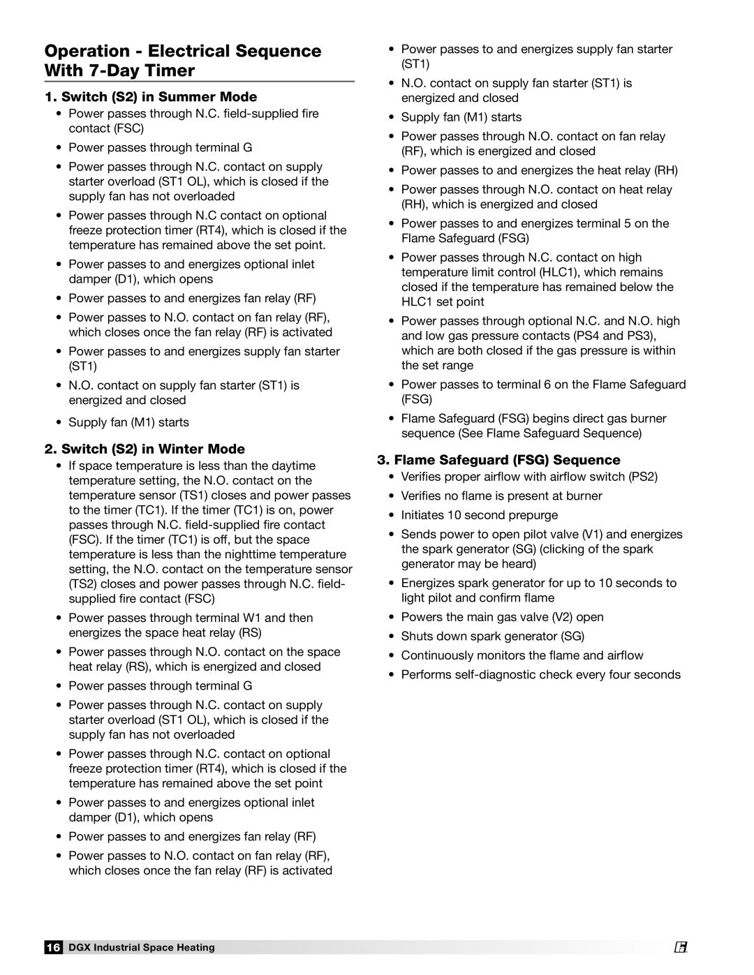
Operation - Electrical Sequence With 7-DayTimer
Models:
Part #470655
1
16
32
32
Download
32 pages
30.25 Kb
13
14
15
16
17
18
19
20
Troubleshooting
Install
Flame Signal Check
Without 7-DayTimer
Uncross wires and reconnect
Warranty
Maintenance
Correct gas pressure and reset
Wire Accessories
Adjust drives as needed
Page 16
Image 16
Page 15
Page 17
Page 16
Image 16
Page 15
Page 17
Contents
General Safety Information
2.Do not touch electrical switches
If you smell gas 1.Open windows
3.Extinguish any open flame
Inspection and Maintenance during Storage
Receiving
Unpacking
Handling
Table of Contents
Clearance to Combustibles / Service Clearances
Installation
Troubleshooting
Installation of Indoor Unit
1. Install Hangers
2. Install Unit
3. Seal Wall Opening
Installation of Arrangement DB / HZ
1.Install Curb and/or Equipment Supports
2. Install Ductwork
4. Install Unit
Installation of Diffuser and Remote Panel TSCP
1. Install Diffuser
2. Install TSCP
Airflow
Installation of Electrical Wiring
1.Determine the Size of the Main Power Lines
3.Connect the Main Power
4. Wire the Optional Convenience Outlet
Installation of Gas Piping
2.Install Additional Regulator if Required
1.Determine the Supply Gas Requirements
3. Connect the Supply Gas Line
Start-Up- Blower
4. Pipe the Optional Vent Line
5. Test the System for Leaks
Pre Start-UpCheck
5.Air Volume Measurement and Check
2.Check the Blower Rotation
3. Check for Vibration
4. Motor Check
Start-UpDirect Gas
Start-UpDirect Gas • 100% Outside Air
1. Check the Supply Gas Pressure
4a. Set the Burner Air Pressure Differential
Start-UpDirect Gas 50/50 Recirculation
4b. Set the Burner Air Pressure Differential
5. Set the Low Fire Time Delay
6. Set the Maximum Firing Rate
Start-UpDirect Gas continued
Regulators and Modulating Valves
7. Set the Minimum Firing Rate
8. Set Daytime Temperature
11.Flame Signal Check
9. Set Nighttime Temperature
10.Program the 7 Day Time Clock
Flame Signal Check
Without 7-DayTimer
1.Switch S2 in Summer Mode
2.Switch S2 in Winter Mode
3.Flame Safeguard FSG Sequence
Operation - Electrical Sequence With 7-DayTimer
1.Switch S2 in Summer Mode
2.Switch S2 in Winter Mode
3.Flame Safeguard FSG Sequence
Troubleshooting
Blower Does Not Operate
Turn Supply Switch S2 On
Reset
Motor Overamps
Troubleshooting
Reference Blower Start-Up- Step #5
Reference Blower Start-Up- Step #2
Insufficient Airflow
Too Much Airflow
Troubleshooting
Reference Filters in the Maintenance section
Troubleshooting
Excessive Noise or Vibration
Reference Bearings in the Maintenance section
Heater Does Not Operate
Troubleshooting
Turn Heat Switch S4 On
Wire Heat Switch S4
Troubleshooting
Uncross wires and reconnect
If problems remain, consult the factory
Heater Does Not Operate
Troubleshooting
Adjust drives as needed
Heater Does Not Operate
Reference Direct Gas Start-Up- Step #11
Maintenance - Routine
Snow Accumulation
Motors
Wheels
Bearings
Filters
Maintenance - Fall
High Limit
Burner
Gas Train
Typical Gas Train Layout 400 – 800 MBH
Reference
DGX Industrial Space Heating
Dirty Filter Switch
Typical Control Center Layout
Reference
28 DGX Industrial Space Heating
Start-UpChecklist
Typical setting 5 minutes 45ºF
Typical setting varies
Reference
Maintenance Log
Maintenance Log
Warranty
Copyright 2012 Greenheck Fan Corporation
Top
Page
Image
Contents