SECTION 4: ADJUSTMENTS
Controls
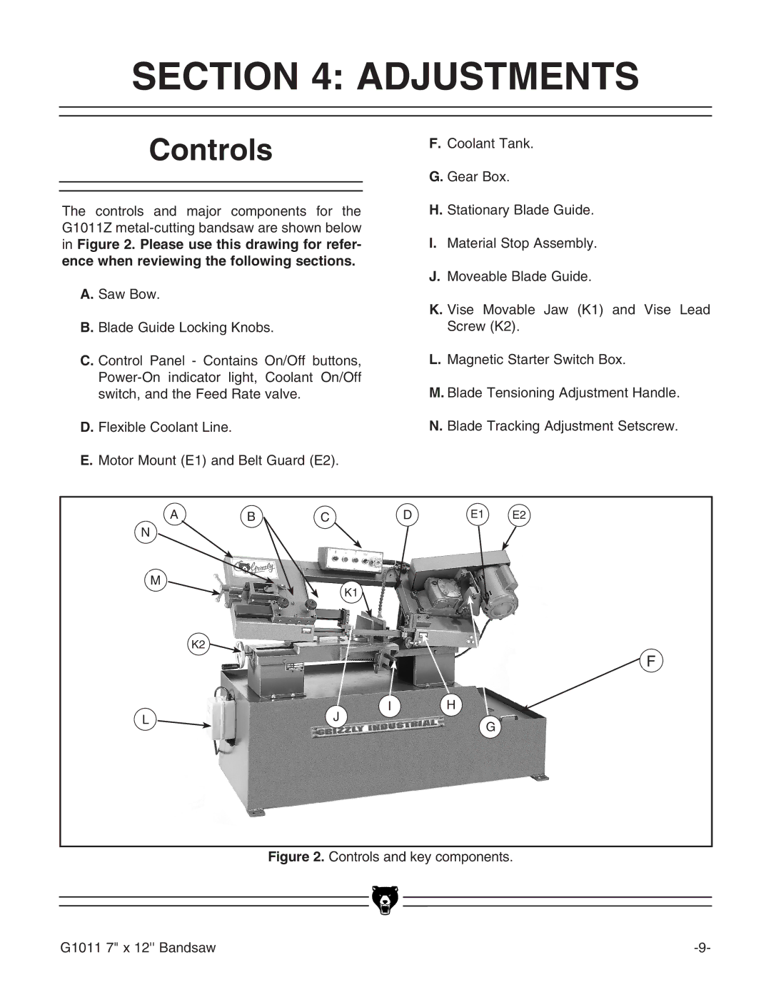
The controls and major components for the G1011Z
A. Saw Bow.
B. Blade Guide Locking Knobs.
F.Coolant Tank.
G.Gear Box.
H.Stationary Blade Guide.
I.Material Stop Assembly.
J.Moveable Blade Guide.
K.Vise Movable Jaw (K1) and Vise Lead Screw (K2).
C. Control Panel - Contains On/Off buttons,
D. Flexible Coolant Line. E. Motor Mount (E1) and Belt Guard (E2).
L.Magnetic Starter Switch Box.
M.Blade Tensioning Adjustment Handle.
N.Blade Tracking Adjustment Setscrew.
A
N
M
K2 ![]()
L
B
C | D | E1 | E2 |
|
|
|
K1
F
J | I | H |
| G | |
|
|
Figure 2. Controls and key components.
G1011 7" x 12'' Bandsaw |