Blade Guides
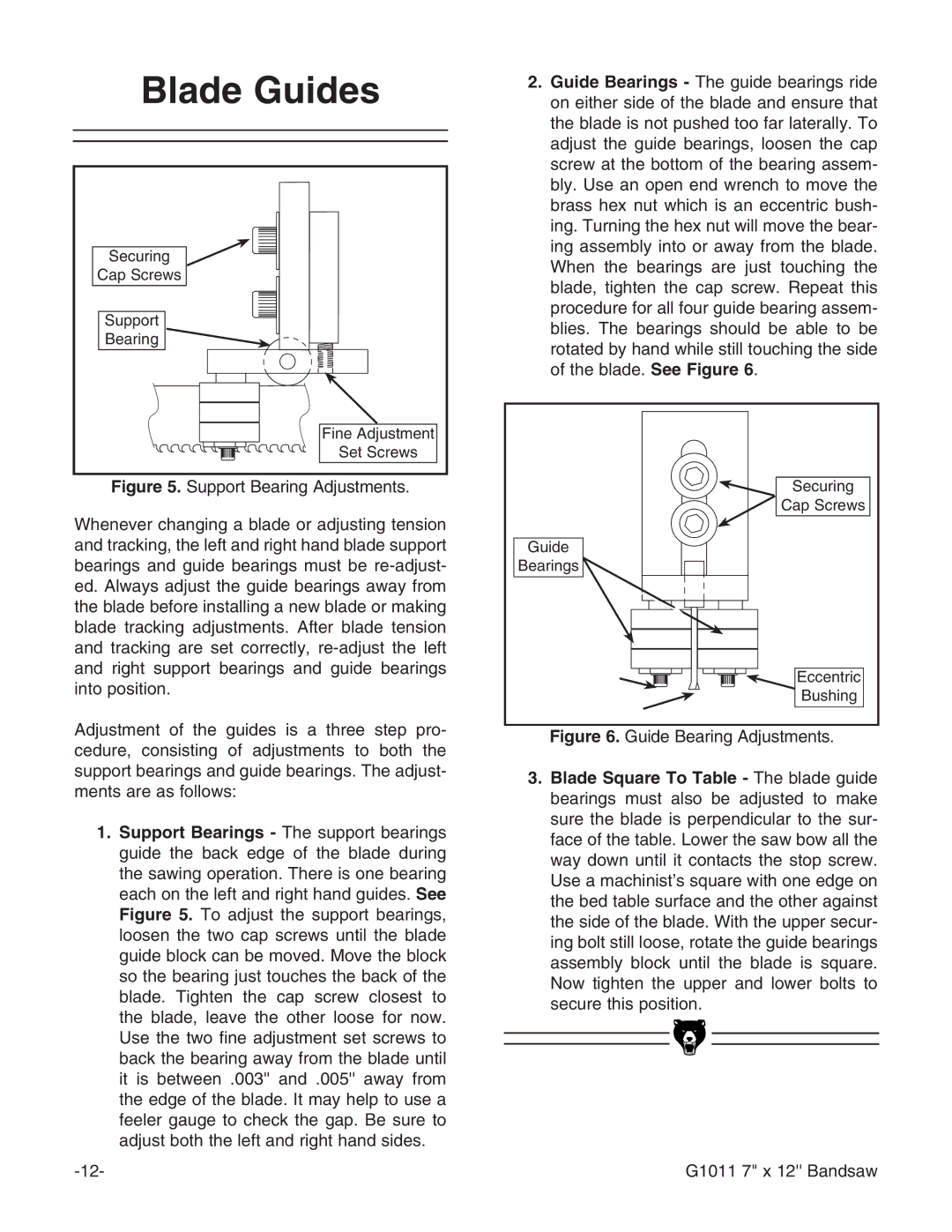
Securing
Cap Screws ![]()
Support
Bearing ![]()
![]()
Fine Adjustment
Set Screws
Figure 5. Support Bearing Adjustments.
Whenever changing a blade or adjusting tension and tracking, the left and right hand blade support bearings and guide bearings must be re-adjust- ed. Always adjust the guide bearings away from the blade before installing a new blade or making blade tracking adjustments. After blade tension and tracking are set correctly, re-adjust the left and right support bearings and guide bearings into position.
Adjustment of the guides is a three step pro- cedure, consisting of adjustments to both the support bearings and guide bearings. The adjust- ments are as follows:
1.Support Bearings - The support bearings guide the back edge of the blade during the sawing operation. There is one bearing each on the left and right hand guides. See Figure 5. To adjust the support bearings, loosen the two cap screws until the blade guide block can be moved. Move the block so the bearing just touches the back of the blade. Tighten the cap screw closest to the blade, leave the other loose for now. Use the two fine adjustment set screws to back the bearing away from the blade until it is between .003'' and .005'' away from the edge of the blade. It may help to use a feeler gauge to check the gap. Be sure to
adjust both the left and right hand sides.
2.Guide Bearings - The guide bearings ride on either side of the blade and ensure that the blade is not pushed too far laterally. To adjust the guide bearings, loosen the cap screw at the bottom of the bearing assem- bly. Use an open end wrench to move the brass hex nut which is an eccentric bush- ing. Turning the hex nut will move the bear- ing assembly into or away from the blade. When the bearings are just touching the blade, tighten the cap screw. Repeat this procedure for all four guide bearing assem- blies. The bearings should be able to be rotated by hand while still touching the side of the blade. See Figure 6.
Securing |
Cap Screws |
Guide |
Bearings |
Eccentric |
Bushing |
Figure 6. Guide Bearing Adjustments. |
3.Blade Square To Table - The blade guide bearings must also be adjusted to make sure the blade is perpendicular to the sur- face of the table. Lower the saw bow all the way down until it contacts the stop screw. Use a machinist’s square with one edge on the bed table surface and the other against the side of the blade. With the upper secur- ing bolt still loose, rotate the guide bearings assembly block until the blade is square. Now tighten the upper and lower bolts to secure this position.
G1011 7" x 12'' Bandsaw