Feed Rate
The lever at the bottom of the headstock changes the feed rate, or the number of threads-
Figure 10. Feed rate selector lever.
The machine plate describes some of the more typical settings which might be used. Figure 11 shows the feed rate portion of the machine plate. Looking at the first column, this means that a feed rate of .0023'' can be achieved by putting the feed lever in position 9 with a 28 tooth gear installed at A, and 80 tooth gears at B and C.
Threading feed rates are described in Figures 12 and 13. An 8 thread per inch feed is the result of having a 60 tooth gear at A, a 30 tooth gear at B, and the lever in position 1.
A metric 2mm pitch requires the lever to be in position 7 and would use the same A and B gears installed above. However the gear between them changes from a 120 tooth to a 127 tooth. Also note that the alignment of gears A and B are off- set so that A now engages the 127 tooth gear and B engages the 120 tooth gear. The shaft for posi- tion B is provided with a spacer which can be installed behind the gear to change its position.
Figure 11. Feed rates portion of machine plate.
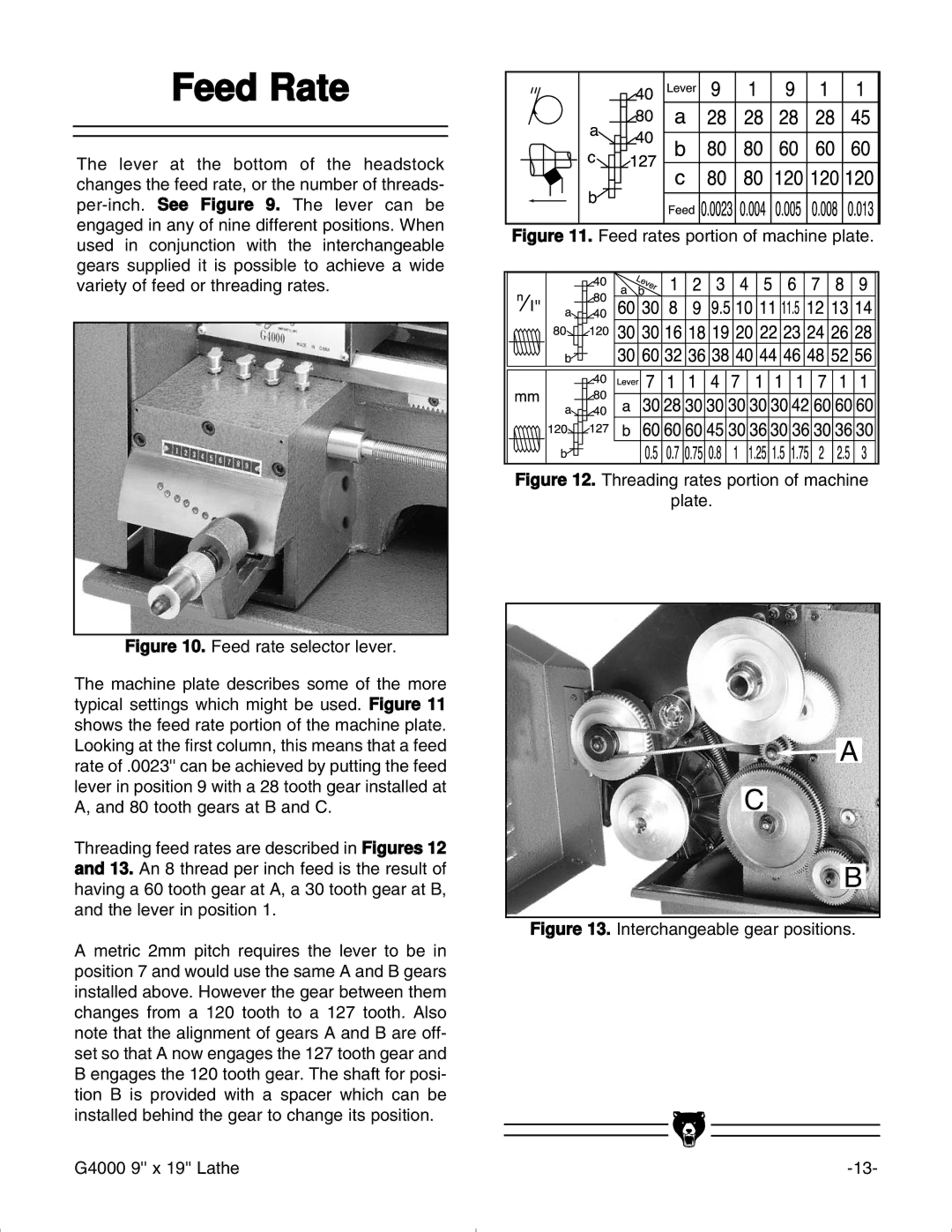
Figure 12. Threading rates portion of machine
plate.
![]() A
A
C
B
Figure 13. Interchangeable gear positions.
G4000 9'' x 19'' Lathe |