Thread Cutting
Several different threads can be cut using the proper combination of gears and settings. When cutting inch threads, the half nut and threading dial are used to thread in a conventional manner. Figure 34. The thread dial chart specifies at which point a thread can be entered using the threading dial.
Metric Thread Cutting - The only difference in metric thread cutting is, the half nut must remain engaged during the entire threading process. The thread dial cannot be utilized.
Set the machine up for the desired thread pitch. Start the machine and engage the half nut. When the tool reaches the workpiece, it will cut the ini- tial threading pass. When the tool reaches the end of the cut, stop the machine by turning the motor off and at the same time back the tool out of the workpiece so that it clears the thread. Do not disengage the half nut lever. Reverse the motor direction to allow the cutting tool to traverse back to the starting point. Repeat these steps until you have obtained the desired results.
Figure 34. Half nut and threading dial.
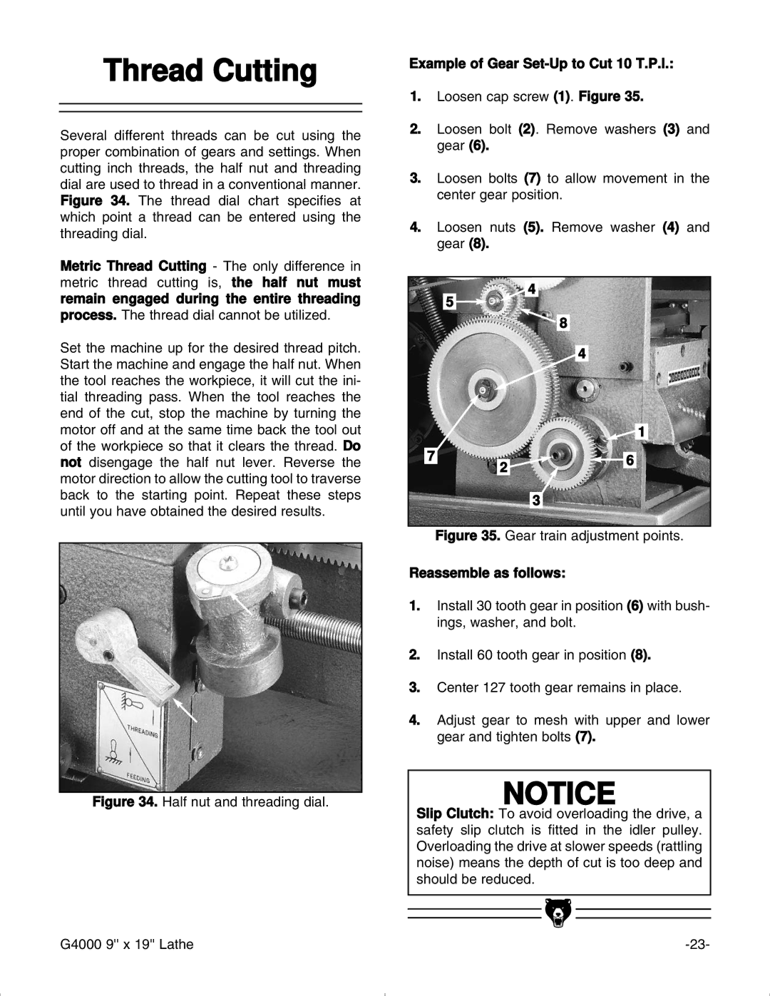
Example of Gear Set-Up to Cut 10 T.P.l.:
1.Loosen cap screw (1). Figure 35.
2.Loosen bolt (2). Remove washers (3) and gear (6).
3.Loosen bolts (7) to allow movement in the center gear position.
4.Loosen nuts (5). Remove washer (4) and gear (8).
4
5
8
4
![]() 1
1
7 | 2 | 6 |
| ||
|
|
3
Figure 35. Gear train adjustment points.
Reassemble as follows:
1.Install 30 tooth gear in position (6) with bush- ings, washer, and bolt.
2.Install 60 tooth gear in position (8).
3.Center 127 tooth gear remains in place.
4.Adjust gear to mesh with upper and lower gear and tighten bolts (7).
NOTICE
Slip Clutch: To avoid overloading the drive, a safety slip clutch is fitted in the idler pulley. Overloading the drive at slower speeds (rattling noise) means the depth of cut is too deep and should be reduced.
G4000 9'' x 19'' Lathe |