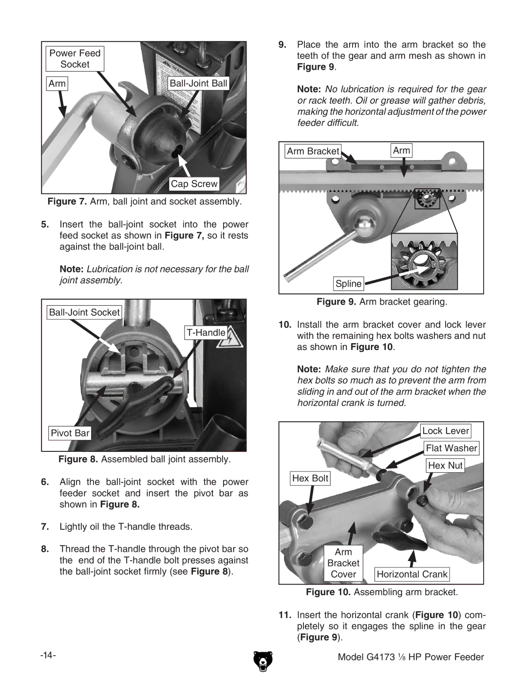
Power Feed
Socket
Arm
Cap Screw
9.Place the arm into the arm bracket so the teeth of the gear and arm mesh as shown in
Figure 9.
Note: No lubrication is required for the gear or rack teeth. Oil or grease will gather debris, making the horizontal adjustment of the power feeder difficult.
Arm Bracket |
| Arm | |
|
|
|
|
|
|
|
|
Figure 7. Arm, ball joint and socket assembly.
5.Insert the ball-joint socket into the power feed socket as shown in Figure 7, so it rests against the ball-joint ball.
Note: Lubrication is not necessary for the ball joint assembly.
Ball-Joint Socket
T-Handle
Pivot Bar
Figure 8. Assembled ball joint assembly.
6.Align the ball-joint socket with the power feeder socket and insert the pivot bar as shown in Figure 8.
7.Lightly oil the T-handle threads.
8.Thread the T-handle through the pivot bar so the end of the T-handle bolt presses against the ball-joint socket firmly (see Figure 8).
Spline 

Figure 9. Arm bracket gearing.
10.Install the arm bracket cover and lock lever with the remaining hex bolts washers and nut as shown in Figure 10.
Note: Make sure that you do not tighten the hex bolts so much as to prevent the arm from sliding in and out of the arm bracket when the horizontal crank is turned.
| Lock Lever |
| Flat Washer |
| Hex Nut |
Hex Bolt |
|
Arm |
|
Bracket |
|
Cover | Horizontal Crank |