4.Remove the springs that are in the setscrew holes. See Figure 42.
5.Check for any dirt or grit, and clean the springs and setscrews if dirty.
6.Screw the three
7.Screw the light pressure setscrew (Figure 42) until it is approximately 1⁄4" above the head casting. The feed chain applies addi- tional tension to the right side of the outfeed roller, so the pressure added by the setscrew need not be as high.
Pressure Setscrew |
|
Pressure Spring |
|
Roller |
|
Check Nut | Height Setscrew |
|
Figure 42. Roller pressure assembly.
Chip Deflector
The chip deflector keeps chips from falling onto the outfeed roller. It is the orange plastic plate located under the top cover.
The beveled edge of the chip deflector should be properly adjusted according to your dust collec- tion setup. However, if the chip deflector is set too close to the knives, the rotating cutterhead may pull it in and destroy it.
To adjust the chip deflector:
1.Disconnect the machine from the power source!
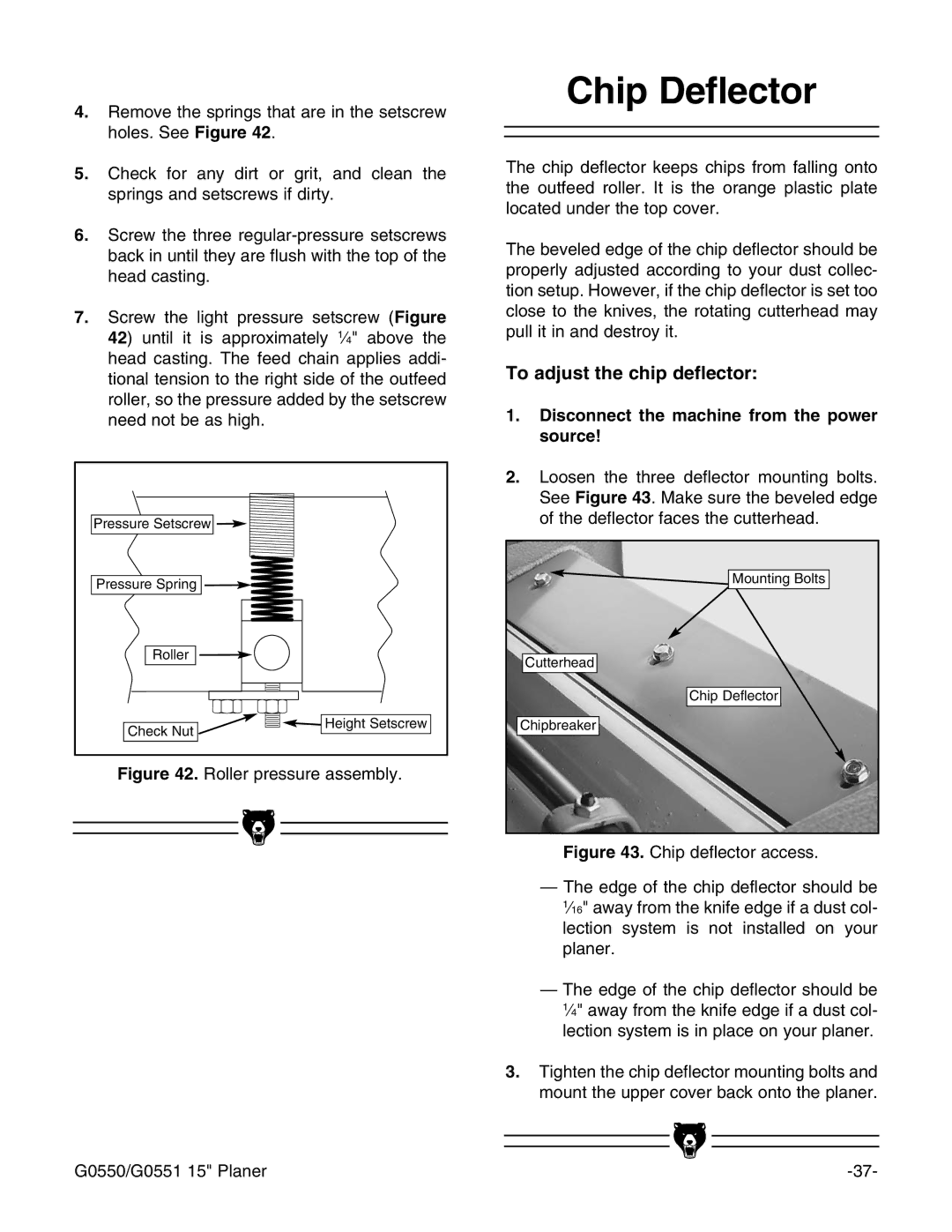
2.Loosen the three deflector mounting bolts. See Figure 43. Make sure the beveled edge of the deflector faces the cutterhead.
Mounting Bolts |
Cutterhead |
Chip Deflector |
Chipbreaker |
Figure 43. Chip deflector access.
—The edge of the chip deflector should be 1⁄16" away from the knife edge if a dust col- lection system is not installed on your planer.
—The edge of the chip deflector should be 1⁄4" away from the knife edge if a dust col- lection system is in place on your planer.
3.Tighten the chip deflector mounting bolts and mount the upper cover back onto the planer.
|
|
|
|
|
|
|
|
|
|
|
|
G0550/G0551 15" Planer | |||