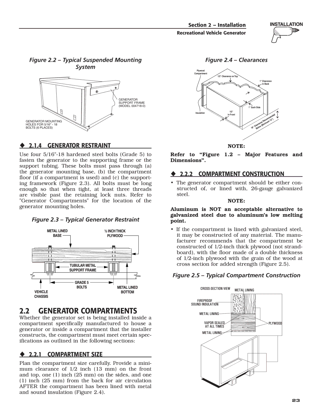
Figure 2.2 – Typical Suspended Mounting
System
Section 2 – Installation
Recreational Vehicle Generator
Figure 2.4 – Clearances
GENERATOR SUPPORT FRAME (MODEL
GENERATOR MOUNTING
HOLES FOR 5/16" - 18
BOLTS (6 PLACES)
Plywood
Compartment
1/2" Clearance on Top
Insulation | 1/2" | |
in Front | ||
|
1" Clearance | |||
| in Back |
| |
1" Each Side |
|
|
|
|
| mended | |
Cleara |
| Recom | 12") |
(Minimum |
| ||
nce |
|
| |
18" Below |
|
|
|
2.1.4 GENERATOR RESTRAINT
Use four
Figure 2.3 – Typical Generator Restraint
NOTE:
Refer to “Figure 1.2 – Major Features and Dimensions”.
2.2.2 COMPARTMENT CONSTRUCTION
•The generator compartment should be either con- structed of, or lined with,
NOTE:
Aluminum is NOT an acceptable alternative to galvanized steel due to aluminum’s low melting point.
•If the compartment is lined with galvanized steel, it may be constructed of any material. The manu- facturer recommends that the compartment be constructed of
Figure 2.5 – Typical Compartment Construction
2.2 GENERATOR COMPARTMENTS
Whether the generator set is being installed inside a compartment specifically manufactured to house a generator or inside a compartment that the installer constructs, the compartment must meet certain spec- ifications as outlined in the following sections:
2.2.1 COMPARTMENT SIZE
Plan the compartment size carefully. Provide a mini- mum clearance of 1/2 inch (13 mm) on the front and top, one (1) inch (25 mm) on the sides, and one
(1)inch (25 mm) from the back for air circulation AFTER the compartment has been lined with metal and sound insulation (Figure 2.4).
23