Section 2 – Operation
Recreational Vehicle Generator
2.1 GENERATOR CONTROL PANEL
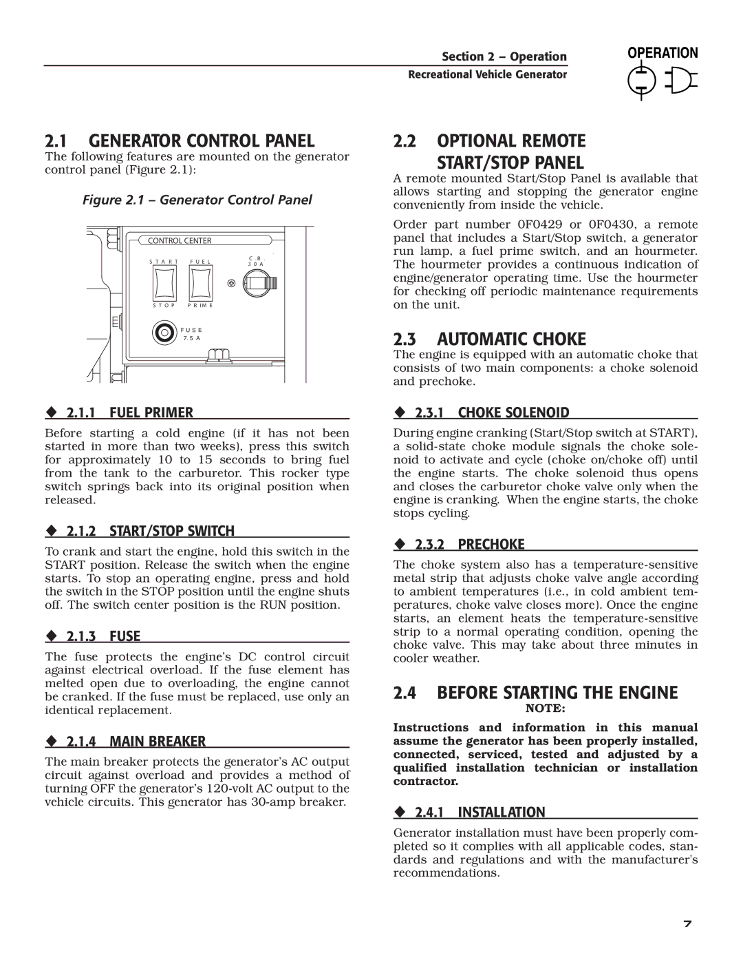
The following features are mounted on the generator control panel (Figure 2.1):
Figure 2.1 – Generator Control Panel
CONTROL CENTER |
| ||
S T A R T | F U E L | C . B . | |
3 0 A | |||
|
| ||
S T O P | P R I M E |
| |
| F U S E |
| |
| 7. 5 A |
| |
2.2 OPTIONAL REMOTE START/STOP PANEL
A remote mounted Start/Stop Panel is available that allows starting and stopping the generator engine conveniently from inside the vehicle.
Order part number 0F0429 or 0F0430, a remote panel that includes a Start/Stop switch, a generator run lamp, a fuel prime switch, and an hourmeter. The hourmeter provides a continuous indication of engine/generator operating time. Use the hourmeter for checking off periodic maintenance requirements on the unit.
2.3 AUTOMATIC CHOKE
The engine is equipped with an automatic choke that consists of two main components: a choke solenoid and prechoke.
2.1.1 FUEL PRIMER
Before starting a cold engine (if it has not been started in more than two weeks), press this switch for approximately 10 to 15 seconds to bring fuel from the tank to the carburetor. This rocker type switch springs back into its original position when released.
2.1.2 START/STOP SWITCH
To crank and start the engine, hold this switch in the START position. Release the switch when the engine starts. To stop an operating engine, press and hold the switch in the STOP position until the engine shuts off. The switch center position is the RUN position.
2.1.3 FUSE
The fuse protects the engine’s DC control circuit against electrical overload. If the fuse element has melted open due to overloading, the engine cannot be cranked. If the fuse must be replaced, use only an identical replacement.
2.1.4 MAIN BREAKER
The main breaker protects the generator’s AC output circuit against overload and provides a method of turning OFF the generator’s
2.3.1 CHOKE SOLENOID
During engine cranking (Start/Stop switch at START),
a
2.3.2 PRECHOKE
The choke system also has a
2.4 BEFORE STARTING THE ENGINE
NOTE:
Instructions and information in this manual assume the generator has been properly installed, connected, serviced, tested and adjusted by a qualified installation technician or installation contractor.
2.4.1 INSTALLATION
Generator installation must have been properly com- pleted so it complies with all applicable codes, stan- dards and regulations and with the manufacturer's recommendations.
7