Section 2 – Installation
Recreational Vehicle Generator
Figure 2.7 – Typical Noise Abatement | 2.3 COOLING AND VENTILATING AIR |
•Line the compartment interior walls and floor, as well as the underside of the floor, with
•Vapor seal all compartment seams and joints.
•Over the galvanized steel lining, install a combi- nation of acoustical materials as mentioned in "Sound Insulating Materials".
![]()
![]() DANGER
DANGER
To prevent fire or explosion, do not install any insulation or other absorbent materials on the interior or underside of the compartment floor.
•Seal all compartment door edges to prevent noise leakage around the door perimeter.
•Line the compartment door interior (except for air openings) with suitable, fireproof sound insulation (such as
2.2.5 COMPARTMENT FLOOR CUTOUTS
Provide openings in the generator compartment for the following items (Figure 2.8 on page 26):
•Engine exhaust and cooling air outlets
•Generator cooling air inlet
•Four holes for passage of generator mounting bolts (see "Generator Restraint").
![]()
![]() DANGER
DANGER
It is absolutely essential that an adequate flow of air for cooling, ventilating and engine combustion be supplied to the generator set. Without sufficient airflow, the engine/generator quickly overheats. Such overheating can cause serious operating difficulties and also may cause fire and personal injury. The installer must make sure that sufficient air is avail- able to the generator for cooling, ventilating and combustion. The installer also must provide for a path for exhausting the cooling air to the exterior of a compartment, if so equipped.
![]()
![]() DANGER
DANGER
Never use discharged cooling air for heating or permit such air to enter the vehicle interior. This air contains deadly carbon monoxide gas and other poisonous, flammable or explosive gases.
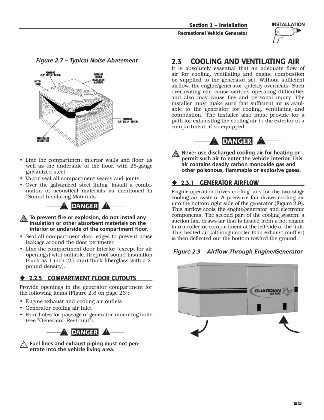
2.3.1 GENERATOR AIRFLOW
Engine operation drives cooling fans for the
Figure 2.9 – Airflow Through Engine/Generator
Fuel lines and exhaust piping must not pen- etrate into the vehicle living area.
25